Download
1 / 13
150 likes | 172 Vues
Design of Hydraulic Turbine. (Low head & High discharge). Objective. Design and analysis of Hydraulic turbine for low head and high discharge ( H 10 to 50 m & Nq 70 to 300 rpm)

E N D
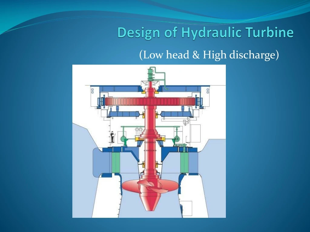
Design of Hydraulic Turbine (Low head & High discharge)
Objective • Design and analysis of Hydraulic turbine for low head and high discharge ( H 10 to 50 m & Nq 70 to 300 rpm) • Design of Kaplan Turbine which is most suitable for available head and discharge ( Head = 15m , Discharge Q = 0.9m3/sec). • Design of Blade profile depending on parameters. • To fullfill low power requirement in remote areas for general use of electricity (Below 150 Kw)
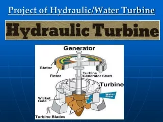
Introduction : Kaplan Turbine • Water flows parallel to axis of rotation of shaft turbine is known as axial flow turbine. • Kaplan turbine is also a reaction turbine. ( part of pressure energy is converted to kinetic energy during flow of water). • Vanes are fixed on hub and hence hub act as runner for axial flow reaction turbine. • In kaplan turbine, unlike all other turbines, the runner's blades are movable. • The radial component of the fluid velocity is negligible. Since there is no change in the direction of the fluid, several axial stages can be used to increase power output
Basic Calculations • Q = 0.9m^3/sec = 900 lts/sec. • H = 15m • Turbine speed = 900 rpm. • Power Output = Rho x g x QH = 133Kw • Specific Work w = gH = 147.15 J/kg • Kinematic or specific speed = 112rpm The expected range of specific speed values is 70 < nq < 300. If the specific speed is less than 70, then you should look at an alternative type of turbine e.g. Crossflow ,pump as turbine. • Kug(From Graph) = 1.31 • [Dh /Dt] (From Graph) = 0.58 • Dt outer dia of runner = 0.476 m & Dh hub dia = 0.276 m • Blade no (Z) = 6
Drunner Dhub Dimensions:
Velocity Calculations • Axial Velocity pi[(Rt)^2 – (Rh)^2] x Vf = Q Vf1 = Vf2 = 7.61m/sec (for axial flow machine) • Peripheral velocity at inlet and outlet u = [pi x Dh x N]/60 u1 = u2 = 13 m/sec • Whirl velocity at inlet and outlet Vw1 & Vw2 ƞ x w = u(Vw1 – Vw2) ƞ(Hydraulic eff) = 0.85(anderson specific speed correction factor) 0.85 x 147.15 = 13(Vw1) Vw1 = 9.62 m/sec Vw2 = 5% Vw1 = 0.481 m/sec
Angle calculations • α = 51.66° • Θ = 23.94° • β = 3.7° • φ= 58.70°
Further project work • Blade profile design. • Runner(Plate blade design). • Spiral casing design. • Catia model. • Analysis of model.