Download
1 / 109
1.88k likes | 2.7k Vues
Safety requirements of Audio , video and similar electronic apparatus IEC 60065/IEC 62368-1. AFSEC 26/27-08-2013 NAIROBI. Jean LANZO Certification Officer. Sommaire. History Scope Objectives and covered risks Safety general principles Terminology The circuits. Grade of Insulation

E N D
Safety requirements of Audio, video and similar electronic apparatusIEC 60065/IEC 62368-1 AFSEC 26/27-08-2013 NAIROBI Jean LANZOCertification Officer
Sommaire History Scope Objectives and covered risks Safety general principles Terminology The circuits • Grade of Insulation • Quantification of insulation • Heating • Resistance to fire • Fault conditions • Television receivers • Philosophy of CEI 62368-1
HISTORY AFSEC 26/27-08-2013 NAIROBI Jean LANZOCertification Officer
HISTORY IEC 60065:1952 (ed 1.0) Safety requirements for electric mains operated radio receiving apparatus IEC 60065:1965 (ed 2.0) Safety requirements for mains operated electronic and related equipment for domestic and similar general use IEC 60950:1986 (ed 1.0) Safety of information technology equipment including electrical business equipment IEC 60950:1991 (ed 2.0) + A1:1992 + A2:1993 + A3:1995 + A4:1996 IEC 60065:1998 (ed 6.0) Audio, video and similar electronic apparatus – Safety requirements 1952 ACOS = Advisory Committee On Safety 1965 1986 1996 07-1998 GUIDE IEC 112:1998 (ed 1.0) by ACOS Guide on the safety of multimedia equipment 09-1998
HISTORY IEC 60065:2001 (ed 7.0) Audio, video and similar electronic apparatus – Safety requirements TC92 IEC 60950-1:2001 (ed 3) Information technology equipment – Safety – Part 1: General requirements TC 74 2001 Evolution of apparatus functionalities High density of electronic components ==> Increase and mixing of functionalities TC 108 = (TC92 + TC 74) IEC 60065:2001 +A1:2005 TC108 IEC 60950-1:2005 TC108 2005 CEI 62368-1 :2010 TC108 2010 2013
SCOPE AFSEC 26/27-08-2013 NAIROBI Jean LANZOCertification Officer
Scope • Electronics apparatus for • reception, generation, recording • Record and reproduction of audio, video and associated signals • Combination of the above apparatus • Household and similar general use • Places of public assembly • School, theatres, • Workplace
Scope • Supplied by: • Mains • External power supply module • Battery • Remote power feeding • At a rated voltage of • 250 V (single phase) or • 433 V (other than single phase) • May be connected to telecommunication network or Cable distribution network of antenna signal
Some apparatus within the scope • Sound and /or image receiver and amplifier (radio, television set, Citizen Band radio etc..); • Supply apparatus intended to supply other apparatus in this standard scope; • Audio and/or video educational apparatus (record player, tape reader, tape walkman and video player, etc..); • Multimedia apparatus; • Beamer; • Video recorder and associated monitors (camera, camcorder, etc..) ; • Electronic gaming and scoring machines; • Juke boxes;
Some apparatus within the scope • Electronic light effect apparatus; • cable head-end receivers; • Antenna signal converters and amplifiers; • Antenna positioners; • Alarm systems apparatus; • Record and optical disc players; • Professional sound/video systems; • Electronic flash apparatus for photographic purposes; • Etc…
Apparatus out of the scope • Film, slide and overhead projectors • IEC 60335-2-56 • gaming and scoring machines for commercial use • IEC 60335-2-82
OBJECTIVES and coveredrisks AFSEC 26/27-08-2013 NAIROBI Jean LANZOCertification Officer
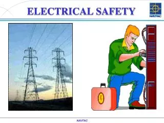
Objectives Standard requirements allow • A protection against: • Hazardous current through human body (electrical choc) • Excessive temperature value • Fire ignition and propagation • Mechanical instability • Injury from mechanical parts • Hazardous radiations • Implosion and explosion effects • Design of a reliable apparatus
Risks of electrical choc • Current flow through human body • Observed physiological effects depend on: • Intensity of the current • Applied voltage and frequency • Body impedance (contact surface, humidity) • Duration of the passage • Current path in the body
Risks of electrical choc • High intensity : directs effects • Burning • Ventricular fibrillation • Low intensity :involuntary reaction • Downfall • Injury • Etc.…
Risks of electrical choc • Direct contact innormal condition • Parts at hazardous voltage • Insulation failure; in fault condition • Rupture of the electric envelope • Contact current
Risks of electrical choc • Short-circuit between high current energy source connectors • Arcing • Emission of molten metal • Burning • Possible risks with low voltage circuits • Battery
Thermal and firerisks • Excessive heating • In normal use • In single fault situation • Overload, • Insulation failure • Ignition, fire • Releasing of connection • Inflammation of liquid
Mechanical risks • Instability • On inclined plane • In full deployment situation • Sharp edges and corners • Moving parts • Projection of particles • Implosion of cathode ray tube (CRT) • Explosion of battery
Radiations risks • Radiations • Lasers and LED • Sound frequencies • Radio frequencies
SAFETY GENERAL PRINCIPLES AFSEC 26/27-08-2013 NAIROBI Jean LANZOCertification Officer
Design principle Safety integration Protect for risks which cannot be removed at the design phase Remove or lower the risk at the design phase Inform the user about the residual risks Marking/Training Goal: cancel all risk during the foreseeable life time of the apparatus : transportation, installation, usage, shutdown and disposal
Design principle • Avoid risks • in normal operation conditions • but also: • In fault condition • In foreseeable unexpected usage • Under external environmental influences (temperature, humidity, altitude, pollution, overvoltage etc…)
Design principle • Choose material and components in such a way that they can: • Operate without being hazard source, during the apparatus life time • Be compatible with the other components • Operate correctly in their ratings • Avoid hazard in single fault condition
Implementation (against electrical choc) Identify type of circuits in the apparatus (Primary, Secondary, Low voltage, Extra-low voltage, Safety Extra low voltage, current limited , Telecommunication network voltage, cable distribution of antenna signal). Determine insulation between: - circuits taken by pairs, - each circuit and accessible part (basic, supplementary, double, reinforced) Verify conformity to standard requirements (creepage distance, clearance, solid insulation, dielectric strength )
TERMINOLGY AFSEC 26/27-08-2013 NAIROBI Jean LANZOCertification Officer
Electrical rating • Mains • power source with voltage > 35 V (peak) a.c. or d.c. • Rated voltage; rated current consumption; rated power consumption; rated frequency; • Values in normal operating condition • Expected to be marked on the apparatus • As an alternative, rated current consumption and rated power consumption may be given in the instruction manual. • “/” for user selectable ratings (120/240 V) • “-” for rating range (120-240 V) • Tolerance = +10%, -10%
Electrical classification • Class I • Basic insulation + earth connection of conductive accessible parts • Class II • Double insulation or reinforced insulation • Class III: Not defined in IEC 60065Defined in IEC 60950-1 and CEI 62368-1 • Apparatus supplied by a SELV circuit or Energy Source class 1 (ES1) and • No internal hazardous voltage or Energy Source class 3 (ES3)
Connection to the mains • Direct connection to the mains • Conductive connection to the mains • Permanently connected apparatus • Needs a tool • Cannot be loosened by hand • Remote power feeding • supply of power to apparatus via a cable network (e.g.: Telecommunication) Apparatus Mains ≥ 9 A ≥ 0,7 mA fuse Mains 2000 Ω Apparatus
Connection to the mains • Pluggable equipment Type A • connection to a mains supply via a non-industrial plug and socket-outlet or a non-industrial appliance coupler, or both • Pluggable equipment Type B • connection to a mains supply via a industrial plug and socket-outlet or an appliance coupler, or both, complying with IEC 60309 • Protective earthing terminal • TERMINAL to which parts are connected and which is required to be connected to earth for safety reasons
Enclosure • Enclosure • housing affording the type and degree of protection suitable for the intended application
Enclosure • The enclosure may be only for one protection • The same enclosure can provide all the three protections. • Decorative enclosure • Is outside the mechanical enclosure of the apparatus • Has no safeguard function
Signals, sources and loads • Noise signal • random signal having normal probability distribution of instantaneous values. • Pink noise • Energy per unit bandwidth inverse, proportional to frequency • Rated load impedance • Output circuit load specified by the manufacturer (4 Ω, 2x8 Ω, 32 Ω etc..)
Signals, sources and loads • Source transducer • Convert the energy of a non electrical signal to electrical energy • Load transducer • convert the energy of an electrical signal into another form of energy • Non-clipped output power • 1000 Hz sine-wave power dissipated at the onset of clipping on either one, or both peaks.
Pollution degree • Pollution degree 1 • No pollution or dry pollution, non-conductive, • Pollution degree 2 • Normal, non-conductive, possibility of temporary conductivity due to condensation • Pollution degree 3 • Conductive pollution area, or non-conductive pollution which could become conductive due • to expected condensation
TYPE OF CIRCUITS AFSEC 26/27-08-2013 NAIROBI Jean LANZOCertification Officer
Type of circuits • Primary • Secondary • Hazardous live voltage • Hazardous energy • Low Voltage • Extra Low Voltage • Safety Extra Low Voltage • Limited current • Telecommunication network • Cable distribution network
Type of circuits • Primary circuit: conductively connected to the mains; may content the following components: • Cables • Primary winding of transformer • Filters components (mainly for EMC reasons) • Motors • Relay • Fan • Fuse • Etc.… • Secondary circuit: not conductively connected to the mains • Separated from primary circuit • Supplied by isolation means: transformer, converter etc…
Type of circuits • Hazardous live voltage • > 35 V peak or 60 V d.c. • > 120 V rms for professional audio apparatus signal • > 71 V rms. for non professional audio apparatus signal • Hazardous energy • Stored charge > 45 µC for charging voltage U: 60 V < U ≤ 15kV peak or d.c. • For charging voltage U > 15 kV peak or d.c., then discharged energy > 350 mJ • Extra Low Voltage (ELV) • ≤ 35 V peak or ≤ 60 V d.c. in normal condition • Hazardous voltage in single fault condition
Type of circuits • Safety Extra Low Voltage (SELV) • ≤ 35 V peak or ≤ 60 V d.c. in normal condition • ≤ 70 V peak or ≤ 120 V d.c. in single fault condition • Separated from hazardous voltage by 3 methods • M1: double insulation or reinforced insulation • M2: basic insulation with screen connected to the earth • M3: basic insulation with secondary circuit connected to the earth • Separated from TNV2 and TNV3 circuit by basic insulation
Type of circuits • Current limited circuits: by construction, the current never become dangerous, regardless the voltage level. • IEC 60065: current (using measuring network), between • any part of the circuit and accessible part (Touch Current) • IEC 60950-1: current (measured through non inductive 2000 Ohms load or using measuring network) between: • any two parts of the circuit, • any part of the circuit and earth • any part of the circuit and accessible part
Type of circuits • Current limited circuits: measuring network • Current limits and measured values in normal conditions • 0,7 mA peak for sinusoidal or mixed signals U2 = 0,35 V peak a.c. • 2 mA d.c. U1 = 1 V d.c. • 70 mA peak for frequency >100kHzU1 = 35 V peak a.c. • Under tropical climate, current limits are multiplied by 2
Type of circuits • Current limited circuits measuring network • Current limits and measured values under single fault • 2,8 mA peak for sinusoidal or mixed signals U2 = 1,4 V peak a.c. • 8 mA d.c. U1 = 4 V d.c. • 140 mA peak for frequency >100kHzU1 = 70 V peak a.c.
Type of circuits • Leakage current: equivalent to « Touch Current » in the protective earthing connection
Type of circuits • Telecommunication network • Metallic wire ended transmission means for communication between two apparatus • May be submitted to atmospheric overvoltage • Telecommunication Network Voltage circuit (TNV) • Located inside the apparatus • Not conductively connected to the mains • Has limited accessible surface • Voltage level limited in normal and in single fault conditions • 4 types: TNV0, TNV1, TNV2 et TNV3
Type of circuits • TNV0 and TNV1 limits same SELV • SELV < (TNV2 and or TNV3) < TNV limits TNV limits
Type of circuits • Summary table for TNV circuits
Type of circuits TNV-3 TNV-3 TNV-1 PABX Analogic interface PABX digital TNV-2 TNV-0
GRADE OF INSULATION AFSEC 26/27-08-2013 NAIROBI Jean LANZOCertification Officer
Grade of insulation • Insulation • Conceptual separation between two circuits or between a circuit and an accessible part. • Basic, supplementary, double or reinforced (electrical choc protection). • Functional • Special case of functional insulation • Not provides protection against electrical choc • Can be used to lower ignition risk (between SELV and protective Earth) • Can be used for EMC reasons (Electro-Magnetic Compatibility )