Download
1 / 9
90 likes | 186 Vues
Clock distribution and absolute time calibration in NEMO phase 1. Martino Ruppi INFN di Bari. Outlook. NEMO phase 1 mini-tower Clock Requirements Clock Shore Station implementation Time data flow The console. NEMO phase 1 mini-tower. Floor Control Module (FCM). FCM

E N D
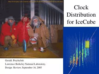
Clock distribution and absolute time calibration in NEMO phase 1 Martino Ruppi INFN di Bari
Outlook • NEMO phase 1 mini-tower • Clock Requirements • Clock Shore Station implementation • Time data flow • The console
NEMO phase 1 mini-tower Floor Control Module (FCM) FCM • Symmetric systems offshore and onshore • Dense Wavelength Division Multiplexing (DWDM) based on passive Add&Drop • Synchronous Protocol FCM onshore offshore • Recovery clock offshore from data flow OM • Front End (FE) and time-stamping in OM • Analog signal sampled at fixed rate (200 MHz) • Data recording triggered when signal exceeds a remotely-setthreshold • The clock recovered by FCM is sent to OM • Synchronous Protocol FCM OM Optical Module (OM & FE) Synchronous protocol 220 m 40 m DWDM Add&Drop 800 Mbps Synchronous protocol 100 m Junction Box
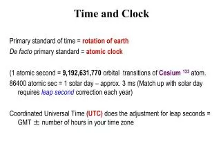
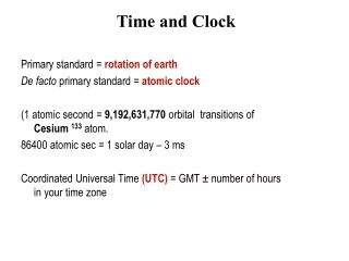
Clock Requirements Time counting in OMs is based on clock recovered in FCM Each onshore FCM has to be synchronized by a low-jitter common clock We need to compare the OM time flow with UTC Onshore clock has to be extracted from GPS clock and time information has to be sent to the apparatus System scaling to KM3 size The clock produced has to guarantee a very high fan-out
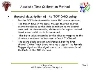
Clock Shore Station • Recovery clock from GPS receiver • Clock Fan-out toward FCMs onshore • Data and time recovery by IRIG B format • UTC data flow sent to FCMs onshore in synchronous protocol • Go-and-Back time measurements with each pair of onshore/offshore FCM by TDC • Network Time Protocol (NTP) server synchronization of PCs by ethernet • TDC 25ps sensitive • GPS receiver (+/-30 ns RMS) • GPS Antenna (now on the roof ot the onshore station) • PC control • Modular PXI Crate FPGA board National Instr. NTP GPS Antenna RS232 GPS Receiver PC IRIG B Ck 10MHz Startx SCSI TDC Connecting Board FPGA Stopx 4 X LVDS Time Data 4Mbit/s 4 X LVDS Ck 4MHz
Data flow protocol to FCM • 8b/10b code (reveling error, scrambling 0/1, byte function embedded) • Time upgraded each 125 s • Data (and Slow-Control) absolute time • Acoustic data absolute time • Room to accomodate more information or commands Data absolute time Acoustic absolute time UTC start sec. min hous days frames since 01/01/2006 sec since 01/01/2006 Idle Idle Idle Idle … Idle stop 500 bit = 1/8000 seconds
The Console (1) LabView enviroment • FPGA Xilinx programming • PC interface • Instrument remote control • Information storage in DB • Logging • Check alarms • Accessible for control through ethernet
The Console (2) Off shore time calibration On shore Time calibration Satellite signal GPS locking FPGA monitoring and management Go and Back time measurements TDC Management
Conclusions • The system is currently working in the NEMO Phase 1 control station • Extension for a full-size 16-floor tower is undergoing (NEMO Phase 2) • The setup can be easily adapted to serve even a KM3-size apparatus (it only needs more modules for the PXI crate)