Download
1 / 36
360 likes | 540 Vues
ICFA AABD Workshop, Chia Laguna, Sardenia. Optical Diagnostics of High-Brightness Electron Beams. Victor A. Verzilov Synchrotrone Trieste. Introduction. “ID” of a high-brightness beam high charge per bunch (1 nC and more) small transverse and longitudinal beam dimensions

E N D
ICFA AABD Workshop, Chia Laguna, Sardenia Optical Diagnostics of High-Brightness Electron Beams Victor A. Verzilov Synchrotrone Trieste
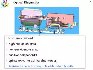
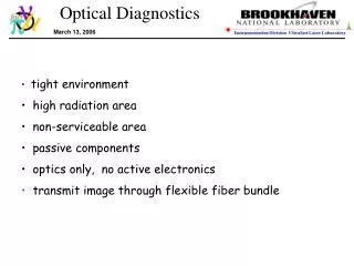
Introduction • “ID” of a high-brightness beam • high charge per bunch (1 nC and more) • small transverse and longitudinal beam dimensions • extremely small normalized emittances • high peak current • space-charge effects in the beam dynamics • Two missions of beam diagnostics • Provide instruments for study of the physics • Assist in delivering high quality beams for applications Every machine is as good as its diagnostics
Introduction (continue) For high-brightness beams control of following parameters is essential • Vertical and horizontal emittances • Transverse beam profile • Beam trajectory • Energy and energy spread • Bunch length • Longitudinal bunch shape • Charge per bunch • Current (peak and average) • Bunch-to-bunch jitter Some of the parameters are measured by traditional methods, others require specific techniques and instrumentations
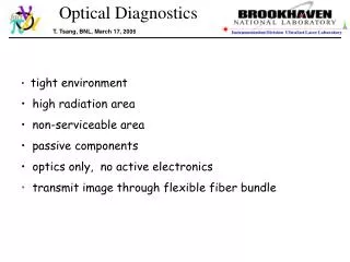
Specific requirements • Take into account space charge forces • Resolution from several millimeters to few tens of micrometers in both longitudinal and transverse plane • Large dynamic range both in terms of beam intensity and measuring interval • Non-invasive • Single-shot • Real time • Jitter-free and synchronized • Usual (stability, reliability ,etc)
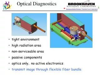
Optical diagnostics and others • Optical diagnostics are based on analysis of photons generated by a beam in related processes or make use of other optical methods (lasers, etc.) • This talk reports the current status of optical diagnostics of high-brightness beams • Reasons • significant progress • make an essential part of available tools • impossible to cover everything • Other techniques • wire scanners • zero phasing • transverse rf deflection cavity • high-order BPM
Outline • Transverse and longitudinalprofile measurements give the largest amount of information about beam parameters • Transverse plane • Spatial resolution is a key issue • Survival problem for intercepting monitors • Non-invasive methods • Emittance measurement issues • Longitudinal plane • Coherent radiation is a primary tool • Direct spectral measurements • Fourier transform • CDR vs CTR • Electro-optical sampling
Transverse planeOTR vs inorganic scintillators at a glance Scintillators (YAG:Ce, YAP:Ce, oth.) • high sensitivity • no grain structure • time response ~ 100ns • conformance to HV • radiation resistance • bulk effect OTR • instantaneous emission • linearity (no saturation effects) • high resolution • surface effect: thickness doesn’t matter • small perturbation to the beam (small thickness) • small radiation background (small thickness) • can be used in a wide range of g • relatively low photon yield (limitation in pepper-pot measurements)
TR spatial resolution OTR resolution is determined by the angular acceptance • FWHM resolution is 2-3 times of the classical PSF • scales as ~ l/q • tails problem; mask can help • high-resolution is experimentally confirmed [CEBAF(4 GeV) SLAC (30 GeV)]
Scintillator resolution A.Murokh et al. BNL-ATF Recent experiment at BNL expressed concerns about micrometer-level resolution. Strong discrepancy in the beam size compared to OTR and wire scans was observed. Q=0.5nC Confirmed at ANL 220 MeV @ 0.8 nC 30-40% discrepancy
Instantaneous heating. TR case N.Golubeva, V.Balandin TTF Si: 1GeV @ 300um. For Al values ten times smaller Temperature limits • Si • Melting - 1683 ° • Thermal stress – 1200° • Al • Melting - 933 ° • Thermal stress – 140-400°
Heating by a bunch train N.Golubeva, V.Balandin TTF • Two cooling processes contribute to the temperature balance • Radiation cooling ~ temperature to the power of 4 • Heat conduction depends on the thermal conductivity and temperature gradient Si@9MHZ Si @ 20 um 9MHz 1nC 20um 1nC 1MHz 50um
90° Thompson scattering W.P.Leemans et al. LBNL 66m FWHM • Noninvasive • Both transverse and longitudinal profiles • Synchronization • Powerful laser • Limited applicability e-beam: 50 MeV@1.5nC laser: 50mJ@0.8m; 50-200fs photons:30keV@105 ph/bunch
Diffraction radiation • Diffraction radiation is emitted when a particle passes in the proximity of optical discontinuities (apertures ) • DR characteristics depend on the ratio of the aperture size to the parameter lg • DR intensity ~ e-a/lgand is strongly suppressed at wavelengths l<a/g
TR vs DR from a slit Transition radiation Diffraction radiation
Effect of the beam size • Angular distribution depends on the relative particle position with respect to the aperture and can be used to measure the beam size • Strong limitation is a low intensity in visible and near infra-red • Energy and angular spread, detector bandwidth are interfering factors • Still has to be proven experimentally A.Cianchi PhD Thesis
Emittance measurement. Multislit vs quadscan S.G.Anderson et all PRSTAB 5,014201(2002) High-brightness beam at “low energy” Widely used techniques • Pepper-pot (multislit) • Quadscan • 3 screens Space-charge forces drift Measure of spaces-charge dominance LLNL 5MeV@50-300pC
Longitudinal plane • Small longitudinal bunches are crucial for many applications • Bunch lengths are on a sub-ps time scale • Conventional methods often do not work • Several new techniques have been developed • Coherent radiation has become a primary tool to measure the bunch length and its shape in the longitudinal plane • It is very powerful tool with nearly unlimited potential towards ever shorter bunches
Radiation from a bunch All particles in a bunch are assumed identical. No angular and energy spread.
Radiation zoo • Any kind of radiation can be coherent and potentially valuable for beam diagnostics • Transition radiation • Diffraction radiation • Synchrotron radiation • Undulator radiation • Smith-Parcell radiation • Cherenkov radiation • Nevertheless, TR is mostly common • Simple • Flat spectrum
Bunch form-factor and coherence • wavelength is much shorter than bunch dimensions • radiation is fully incoherent • particles emit independently • total intensity is proportional to N • wavelength is of the order of bunch dimensions • radiation is partially coherent • some particles emit in phase • increase in total intensity • wavelength is much longer than bunch dimensions • radiation is fully coherent • all particles emit in phase • total intensity is proportional to N2 • F=0 0 <F< 1 F=1
Form-factor and bunch shape Transverse coherence comes first.Unless the beam is microbunched. For the normalized longitudinal distribution of particles in the bunch r(z) By inverse Fourier transform Symmetric bunch
Bunch shape and form-factor Form-factors Bunch shapes with the same rms bunch lengths • Although, in principle, the bunch shape can be retrieved from a measurement, be care, this could be ambiguously. • The bunch size, however, is recovered reliably.
Kramers-Kronig analysis R.Lai and A.J.Sievers NIM A397 Both real and imaginary part of the form-factor amplitude are to be known to recover the asymmetry of the bunch shape. If F(w) is determinedover the entire frequency interval, the Kramers-Kronig relationcan be used to find the phase. By inverse Fourier transform Real part is the observable
Kramers-Kronig analysis.Experiment TESLA TDR • Spectral intensity has to be defined over a significant spectral range. • Errors are produced when asymptotic limit are attached to the data to complete the spectral range. • Front-tail uncertainty. • Analytical properties of the bunch shape function have to be taken into account. Confirmed by recent SASE results!
Single-shot capable Narrow bandwidth Discreteness Polychromator T.Watanabe et al. NIM A480(2002)315 Tokio University 900fs 1.6ps Results are consistent with streak camera and interferometer measurements
Hilbert -Transform spectrometer M.Getz et al., EPAC98 TTF Josephson junction T= 4-78K f= 100-1000GHz • Wide bandwidth • More R&D is necessary
Fourier spectroscopy Coupled to a frequency domain. Measurement in the time domain is a measurement of the autocorrelation of the radiation pulse. • Precise • Established • Time consuming
Low-frequency cut-off • All experimental data suffer to a different extent from the low frequency cut-off. • There is a number of reasons which cause the cut-off: detector band, EM waves transmittance, target size etc. • Data analysis usually consists inassuming a certain bunch shape and varying the size parameter for the best fit to undisturbed data.
Analysis in the time domain (TR case) A.Murokh,J.B.Rosenzweig et al Filter function Model bunch shape Autocorrelation curve Coherent spectrum
TR. Finite-size screen r lg screen The effect comes into play when the screen size is comparable or smaller than lg r=20 mm qd=0.05 rad 2mm 1mm • The TR spectrum from a finite size target is a complex function of the beam energy, target extensions, frequency and angle of emission.
Coherent diffraction radiation M.Castellano et al. PRE 63, 056501 TTF Bunch length was measured for slit widths 0 to 10 mm. Effect of the target finite size was proved.
Coherent diffraction radiation.Result M.Castellano et al. PRE 63, 056501 TTF • DR and TR results are consistent in a wide range of slit widths . • CDR can be successfully used for bunch length measurements. • Very promising for ultra-high power beams, because non-invasive. 225MeV @ 1nC
Electro-optic sampling (EOS) Modulation of the polarization of light traveling through a crystal is proportional to the applied electric field • Noninvasive • Fast response ~40 THz • Linearity&dynamic range • Jitter dependent Collective Coulomb field at R is nearly transverse
EOS Single-shot option Make use of a long pulse with a linear frequency chirp • Single shot • On-line • Nearly jitter-free Bunch time profile is linearly encoded onto the wavelength spectrum
EOS Single-shot option.First prove I.Wilke et al., PRL, v.88, is.2,2002FELIX • Resolution ≈ • Chirp • Pulse width • ~300fs • ~70 fs achievable ( ) e-beam: 46MeV@200pC 0.5x4x4mm3 ZnTe crystal laser: 30 fs@800nm,chirp up to 20ps 1.72 ps
Conclusions • Beam diagnostics has significantly advanced to meet specific requirements of high-brightness beams • Wide choice of available techniques from which one can select • Lack of suitable (simple and reliable) non-invasive methods for measurements in the transverse plane (near-future projects) • In the longitudinal plane CDR is likely OK • Difficulties with measurements at μm and sub-μm level in the transverse plane