Download
1 / 14
140 likes | 225 Vues
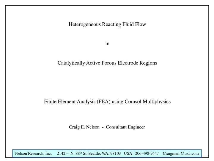
Heterogeneous Reacting Fluid Flow in Catalytically Active Porous Electrode Regions Finite Element Analysis (FEA) using Comsol Multiphysics. Craig E. Nelson - Consultant Engineer. Acknowledgement. The FEA Model Presented here was greatly assisted by the work of Johan Sundqvist

E N D
Heterogeneous Reacting Fluid Flow in Catalytically Active Porous Electrode Regions Finite Element Analysis (FEA) using Comsol Multiphysics Craig E. Nelson - Consultant Engineer
Acknowledgement The FEA Model Presented here was greatly assisted by the work of Johan Sundqvist and his colleagues and academic associates at COMSOL - a publisher of Finite Element Software The porous region geometry I used comes from the pore-scale flow experiments conducted by A. Keller, M. Auset, and S. Sirivithayapakorn at the University of California.
Overview – Volume Averaging Typical analysis starts with the idea that one can average across macroscopic regions
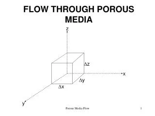
Overview – Microscale Finite Element Modeling (FEA) In this presentation, we will not volume average. We keep the micro-structure and observe how fluid flow and chemical reactions take place. This “Micro-Picture” is very instructive. Here is our domain. It was digitized from an actual porous structure Sealed off Barrier Wall Flow Outlet Side Flow Inlet Side Sealed off Barrier Wall Pink regions are open to flow
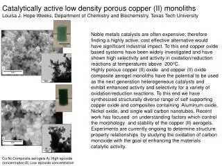
Overview Here is an SEM of the structure from which the pore model was made
Pressure and Flow Velocity Through Porous Regions .1 PSI 0 PSI
Pressure and Flow Velocity Through Porous Regions Overall flow and flux is due to both convection and diffusion .1 PSI Inlet Pressure 0 PSI Outlet Pressure Partially Occluded Region
Flow Velocity Through Porous Regions Partially Occluded Region
Plot of Reynolds Number Through Porous Regions Partially Occluded Region Piezo Pump Performance
Velocity Contours Through Porous Regions Partially Occluded Region
In-flowing Reactant Concentration Field Partially Occluded Region Piezo Pump Performance Concentration is 1 Mole/liter
Inflowing Reactant Flux Partially Occluded Region
Outflowing Reactant Byproduct Concentration Concentration is 1 Mole/liter at the walls and in the cul-de-sacs Occluded Region has high Byproduct Concentration Piezo Pump Performance Byproduct molecules “streaming” Away from a stagnant flow region
Conclusions • 1. A relatively few number of accidental “Choke Points” can easily occlude a relatively • large region that would otherwise be catalytically active. • Reaction byproduct gas bubbles will tend to form in the larger cul-de-sacs • where capillary force bubble compression is low and gas concentration is high. • 3. Once reaction byproduct gas bubbles form, they may remain in place indefinitely • Mass transfer by diffusion processes will be slowed down in porous • regions by the same amount for all reactant and reaction byproduct species. • Catalytic particles in porous regions and coatings are not necessarily electrically • connected to current carrying structure, and thus, may not carry current away from • the reaction sites, as intended