Download
1 / 16
160 likes | 277 Vues
Calice meeting DESY – December 2004. ECAL TB simulation status. Paulo Mora de Freitas, L.L.R. – Ecole polytechnique. Z. X. Ecal prototype implementation. Three independent modules with 1.4, 2.8 and 4.2 mm plates of W Three towers, 3th tower is empty

E N D
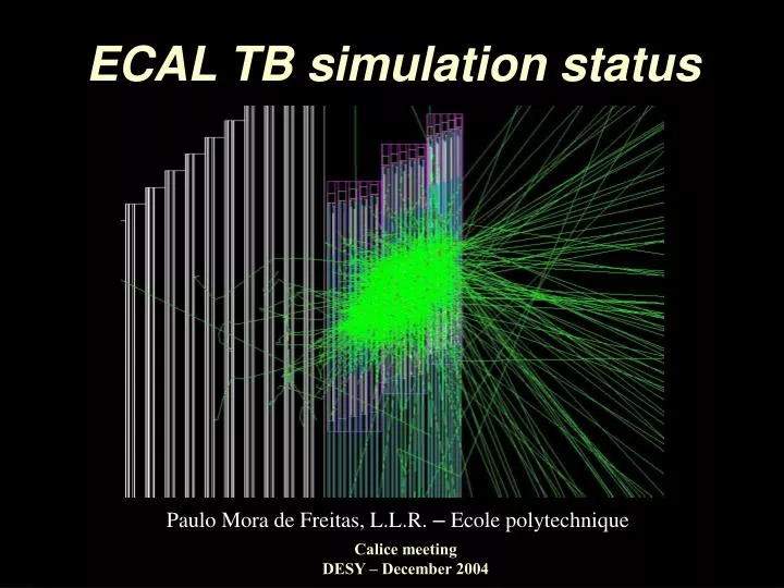
Calice meeting DESY – December 2004 ECAL TB simulation status Paulo Mora de Freitas, L.L.R. – Ecole polytechnique
Z X Ecal prototype implementation Three independent modules with 1.4, 2.8 and 4.2 mm plates of W Three towers, 3th tower is empty Slabs shifted independently in the X direction Shift in the X direction for the two wafer layers in the same slab wafers physically divided into cells Guard-rings also collect hits (virtual concentric squared sections) Implemented by Gabriel Musat (L.L.R.)
Y Z Test beam TB03, zy view Catcher Hcal Ecal Roman Poeschl (DESY), Jeremy McCormick (NIU) Gabriel Musat (LLR)
Y Z Test beam TB03, zy Ecal detail Empty tower Fake wafer
Z X Test beam TB03, zx view Catcher Hcal Ecal
Z X Test beam TB03, zx Ecal detail Fake wafer Fake wafer
Z X Ecal, zx slab shift angles 20,71o 13,89o 16,64o The same step (here 20 mm) for all slabs and for all towers lets to tree different angles for the dead gaps
Z X Test beam TB03, zx max angle (40o)
Z X Ecal placement for zx angle (40o) Centers of the first slabs
Z X Ecal 40o, e- 50 GeV
Angle of the test beam • An ad-doc special init command introduced in the steering file since mokka-03-02 gives the possibility to set up any real value : • /Mokka/init/CONFIG_ANGLE angle Z angle beam X • should disappears as soon as the 3 or 4 different indexed angular configurations will be fixed !
Ecal cell coordinates (Wi, Wj, i, j, k) where : Wi, WJ = indices of the wafer from (1,1) to (3, 3) (the placement and the signal calibration are done per wafer) i, j = indices of the cell inside the wafer from (1,1) to (6,6) (Wi, Wj, I and j increase with the X & Y) k = index of the layer from 1 to 30, increasing with the Z (Wi,Wj,i, j, k) are packed into a single integer word for output and computing convenience CGA provides methods for unpacking and absolute cell center coordinates retrieving for analyses code.
Hits versus odd/even layers The number of hits alternates higher/lower in odd/even layers! First reported by Nigel Watson and David Ward The effect is confirmed also with : the later Mokka and Geant4 versions, with the last Ecal prototype implementation a completely independent G4 application On investigation (thanks to M. Maire, Geant4 team) See the Gabriel’s talk tomorrow
Ecal prototype simulation,conclusions : The implemented model currently includes almost all the relevant details needed for the detector studies. The model is geometry data driven, it should be easy to adapt it for the final configurations (slab shifts, configuration angles, etc) as soon it’ll be fixed. Currently already in use to investigate the number of hits alternating on higher/lower in odd/even layers.