Download
1 / 14
170 likes | 376 Vues
Statics . Chapter 2 Resultant of Coplannar Force Systems. 2-1 Intro . Two systems of forces = equivalent – if produce the same mechanical effect on rigid body Single force that is equivalent to a force system is called the resultant of the force system. 2-2 Vector Representation.

E N D
Statics Chapter 2 Resultant of Coplannar Force Systems
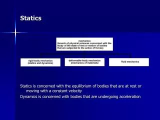
2-1 Intro • Two systems of forces = equivalent – if produce the same mechanical effect on rigid body • Single force that is equivalent to a force system is called the resultant of the force system
2-2 Vector Representation • Figure 2-1 represented graphically by a line segment AB with an arrowhead at one end – length of the line segment AB represents the magnitude of the force - direction is indicated by the angle from the reference axis. • Equal Vectors – two vectors having same magnitude and same direction are said to be equal – figure 2-2 • Negative Vector – two vectors having the same magnitude and opposite direction.
2-3 Resultant of Concurrent Forces • Parallelogram Law – Figure 2-4 shows two vectors are added according to this law • Triangle Rule – the sum of two vectors can also be determined by constructing one half of the parallelogram or triangle • To find the vector sum , we first lay out p at A then lay out Q from the tip of P in a tip to tail fashion, the closing side of the triangle represents the sum of the two vectors • Examples 2-1 • Example 2-2 • Example 2-3
2-4 Rectangular Components • Any two or more forces whose resultant is equal to a force F are call the components of the force • Two mutually perpendicular components are called the rectangular components Fx and Fy are the rectangular components of F in the x and y direction • If the magnitude F and the direction angle of a force are known then from the right triangle • Fx=Fcos @ and Fy = Fsin@ • Counterclockwise measurement is regarded as positive, clockwise measurement as negative
2-4 Rectangular Components • Magnitude and Direction – when the scalar components Fx and Fy of the force F are give , the magnitude of F may be determined from formula 2-3 page 47 • And the reference angle from 2-4 page 47 • Depending on which quadrant the force vector is in the direction angle in the standard position is • First quadrant 0=@ • Second quadrant 0= 180 -@ • Third quadrant 0=180 + @ • Fourth quadrant 0=360-@ • Example 2-4 page 47 • Example 2-5 page 48 • Example 2-6 page 49 • Example 2-7 page 50
2-5 Resultants by Rectangular Components • The resultant of any number of concurrent coplanar forces can be determined by using their rectangular components • Figure 2-9 R=F1 +F2+F3 • Rx = F1x +F2x +f3x • Rx = F1cos @1 + F2cos @2 + F3cos @3 • Ry = F1y +F2y +f3y • Rx = F1sin @1 + F2sin @2 + F3sin @3 • Example 2-8 page 52 • Example 2-9 page 53
2-6 Moment of Force • Effects of a force – force tends to move a body along its line of action – it also tends to rotate a body about an axis • The ability of a force to cause a body to rotate is measured by a quantity called the moment of the force. • Wrench example – rotating moment also called the torque is produced by the applied force depends not only on the magnitude of the force but als on the perpendicular distance d from the center 0 of the bolt to the lne of action of the force • Definition of Moment – two dimensional case – moment of a force about a point ie equal to the magnitude of the force multiplied by the perpendicular distance from 0 to the line of action of the force • Formula 2-7 page 55 • Units of moment are Ib* ft or Ib * in or N* m or kN * m
2-6 Moment of a Force • Direction of Moments – example 2-13 P is CCW and Q is CW • Summation of Moments – CCW will be considered positive CW will be considered negative. • Example 2-10 page 56
2-7 Varignon’s Theorem • States that the moment of a force about any point is equal to the sum of the moments produced by the components of the forces abut the same point • The sum of the moments of the components must be the same as the moment of the force itself • Formula 2-8 page 59 • Principle of transmissibility • The point of application of a force acting on a rigid body may be place anywhere along its line of action – moment arm is clearly independent of the point of application - therefore as long as the magnitude the direction and the line of actin of a force are defined the moment of a force about a given point may b determined by placing the force at any point along its line of actin. • Example 2-11 • Example 2-12
2-8 Couple • Effect of a couple – two equal and opposite forces having parallel lines of actin form a couple – the sum of the moment of the two forces however is not zero – the effect of a couple acting on a rigid body therefore is to cause the rigid body to rotate about an axis perpendicular to the plane of the forces • Moment of a couple – denoting the perpendicular distance between the two forces by d , the moment of a couple about an arbitrary point 0 is equal to formula 2-9 page 63 • Since 0 is an arbitrary point – the moment of a couple about any point is equal to the magnitude of the forces times the perpendicular distance between the forces. • Equivalent couples – two couples acting on the same plane or parallel planes are equivalent if they have the same moment acting in the same direction • Addition of Couples – addition of two or more couples in a plane or parallel planes is the algebraic sum of their moments • Example 2-13 page 63 • Example 2-14 page 64
2-9 Replacing a Force with a Force couple system • Two systems of forces are said to be equivalent if they produce the same mechanical effect on a rigid body – • Equivalent force systems – are said to be equivalent if they have the same resultant force and the same resultant moment about the same point • Force couple system – move a force to another point using the principle of transmissibility – we may add two equal and opposite forces without altering the mechanical effect of the original force – figure 2-17 page 66
2-10 Resultant of a nonconcurrent coplanar force system • In this system there are no point of concurrency – so the locating of the line of action of the resultant is not immediately known • Choose convenient x and y coordinate axes and then resolve each force into rectangular components – formula 2-11 • Example 2-16 page 68 • Example 2-17 page 69 • Example 2-18 page 70
2-11 Resultant of Distributed Line Loads • Distributed Load – occurs whenever the load applied to a body is not concentrated at a point – could be exerted along a line , over a area, or throughout an entire solid body • Load intensity – distributed load along a line is characterized by a load intensity expressed as force per unit length. • Examples 1000 Ib/ft , 1 kip/ft, 1 N/m or 1kn/m • Uniform load – distributed load with a constant intensity is called uniform load – represented with a load diagram – shape like rectangular block • Triangular load – distributed load whose intensity varies linearly from zero to a maximum intensity – represented as triangle • Equivalent concentrated force – to determine the resultant of a force system – each distributed load may be replaced by its equivalent concentrated force • Example 2-19 page 74 • Example 2-20 page 75 • Example 2-21 page 76