Download
1 / 42
420 likes | 608 Vues
Logical Database Design (2 of 3). John Ortiz. Finding All Candidate Keys (cont.). Method 2 (manual approach): Step 1: Draw the dependency graph of F. Each vertex corresponds to an attribute. Edges can be defined as follows: A B becomes A B

E N D
Logical Database Design (2 of 3) John Ortiz
Finding All Candidate Keys (cont.) Method 2 (manual approach): Step 1: Draw the dependency graph of F. Each vertex corresponds to an attribute. Edges can be defined as follows: A B becomes A B A BC becomes A B C AB C becomes A B C Logical Database Design (2)
Finding All Candidate Keys (cont.) Step 2: Identify the set of vertices Vni that have no incoming edges. Step 3: Identify the set of vertices Voi that have only incoming edges. Step 4: A candidate key is a set of attributes that • contains all attributes in Vni • contains no attribute in Voi • has no subset that is already a candidate key Logical Database Design (2)
A H B C G I An Example Using Method 2 Consider R(A, B, C, G, H, I), and F = {A BC, CG HI, B H } Vni = {A, G}, Voi = {H, I}. Since (AG)+ = ABCGHI, AG is the only candidate key of R. Logical Database Design (2)
A B C D E H Another Example Using Method 2 Consider R(A, B, C, D, E, H), and F = {A B, AB E, BH C, C D, D A } Vni = { H }, Voi = { E }. Candidate keys: AH, BH, CH, DH. Logical Database Design (2)
Normal Forms • If a relation is in a certain normal form (BCNF, 3NF, …), certain types of redundancy is known to be avoided/eliminated. • A relation schema R is in First Normal Form (1NF) if every attribute of R takes only single and atomic values. • Every relation is in 1NF • 1NF allows all kinds of redundancy • Higher normal forms are defined in terms of FDs. Logical Database Design (2)
Second Normal Form (2NF) Let F be a set of FDs satisfied by R. • An attribute of R is prime if it appears in a candidate key (according to F) of R. • Y is fully functionally dependent on X if F implies X Y, but not W Y where W X. • R is in Second Normal Form (2NF) if every non-prime attribute of R is fully functionally dependent of every candidate key. • If a part of a candidate key can determine a non-prime attribute, R is not in 2NF. Logical Database Design (2)
2NF: Examples (1) Consider F = {B AH, L CAt} over relation Bank-Loans (Bank, Assets, Headquarter, Loan#, Customer, Amount) • B A is in F+, where A is non-prime, & B is not a candidate key. Bank-Loans is not in 2NF. (2) Consider F = {S NMG, M AO} over Students(SID,Name,Major,GPA,Advisor,Office) • S is the only candidate key, and has a single attribute. Students is in 2NF. • 2NF relations still allow unwanted redundancy Logical Database Design (2)
Another Definition of 2NF • R is in 2NF if for every FD X Y in F+, • Y X (trivial); or • every attribute in Y is prime; or • X is not a proper subset of any candidate key. • R is in 2NF if every candidate key is a single attribute Logical Database Design (2)
Third Normal Form (3NF) Let F be a set of FDs satisfied by R. • R is in Third Normal Form (3NF) if for every FD X A in F+, (a) A X (trivial); or (b) every attribute in A is prime; or (c) X is a superkey. • Let X be a candidate key. If Y B F+, B Y, B is non-prime, and Y is not a super key, then B is non-trivially transitively dependent of X. 3NF removes this dependency. Logical Database Design (2)
3NF: Examples (1) Consider F = {S NASaDn, Dn Ds} over Employees (SSN, Name, Age, Salary, Dept_name, Dept_manager_SSN) • Employees is not in 3NF due to Dn Ds. (2) Consider F = { CS Z, Z C } over R(City, Street, Zipcode) • R is in 3NF as each attribute is prime (How many candidate keys are there?). • 3NF may still have redundancy (introduced by Z C) Logical Database Design (2)
Boyce-Codd Normal Forms (BCNF) Let F be a set of FDs over R. • R is in Boyce-Codd Normal Form (BCNF) if for every FD X A in F+, (a) A X (trivial); or (b) X is a superkey. Example: Consider R(City, Street, Zipcode) and F = { CS Z, Z C }. R is in 3NF but not in BCNF because in Z C, Z is not a superkey. Logical Database Design (2)
Normal Forms: Summary • BCNF 3NF 2NF 1NF • 2NF removes some insertion anomalies and deletion anomalies. Also removes redundancies caused by partial dependencies on key. • 3NF removes all insertion anomalies and deletion anomalies. Also removes redundancies caused by transitive dependencies. • BCNF achieves all that are achieved by 3NF, and removes all redundancies caused by FDs. Logical Database Design (2)
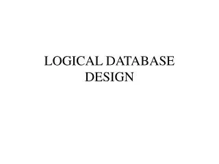
Normalize the Following Relation • Universal Relation R • (A, B, {C, D, K}, E, F(G, H, I), J) • Given: • A B, C DK, E F, F GHI, K EJ • A:C is M:N, C:K is 1:M (C is the many), K:E is 1:M (E is the many) • What do the parenthesis indicate? • What do the braces indicate? Logical Database Design (2)
A G H F B I K J R C D E E-R Diagram - Unnormalized Logical Database Design (2)
Normalize the Following Relation • Universal Relation R • (A, B, {C, D, K}, E, F(G, H, I), J) • Given: • A B, C DK, E F, F GHI, K EJ • Step 1: Remove any composite attributes • Either determine that the level of detail provided by G, H, I is unnecessary • OR remove F • For our purposes we will remove F Logical Database Design (2)
Normalize the Following Relation • New Universal Relation R • (A, B, {C, D, K}, E, G, H, I, J) • Given: • A B, C DK, E GHI, K EJ • Step 2: Remove any multi-valued attributes • If there is a determinant within the MV attributes, make it part of the key • AC BDK Logical Database Design (2)
Proof • Given: A B • (IR2) AC BC (augmentation) • (IR4) AC B (decomposition) • Given: C DK • (IR2) AC DK • (IR5) AC BDK (union) Logical Database Design (2)
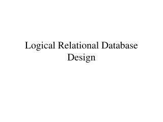
1NF • 1NF Universal Relation R • R(A, B, C, D, E, G, H, I, J, K) • Given: • AC BD, A B, C DK, E GHI, • K EJ • Find all Candidate Keys: • Vni (A C), Voi (B D G H I J), E, K have both • A determines BDK, in which K dets EJ, in which E dets GHI and C determines DK • Only Candidate Key is AC Logical Database Design (2)
A G H B I K J C D E R E-R Diagram - 1NF Logical Database Design (2)
Update Anomalies in 1NF • R(A, B, C, D, E, G, H, I, J, K) • AC BDK, A B, C DK, E GHI, • K EJ • Identify Partial Dependencies: • A B, C DK • Can’t insert an ‘A’ without a ‘C’ (vice/versa) • If you delete an ‘A’ may lose info about ‘C’ • What info would you lose? • If you change a ‘B’, may have to change in multiple places Logical Database Design (2)
Going to 2NF • REMOVE PARTIAL DEPENDENCIES • R(A, B, C, D, E, G, H, I, J, K) • AC BDK, A B, C DK, E GHI, K EJ • R1(A, B) • R2(C, D, K, E, G, H, I, J) • Given: A:C is M:N, therefore we need what? • R3(A, C) What is the PK for R3? • Identify the FK(s). • Check: Are we in 2NF? • Part. Deps. in R1?, R2? Logical Database Design (2)
I E C J K D G B A H R1 R2 R3 E-R Diagram – 2NF M N Logical Database Design (2)
Update Anomalies in 2NF • R1(A, B), R2(C, D, K, E, G, H, I, J), R3(A, C) • Identify Transitive Dependencies: • Given: A B, C DK, E GHI, K EJ • C K, K E, E GHI • Can’t insert an ‘K’ without a ‘C’ (NOT vice/versa) • If you delete an ‘C’ may lose info about ‘K’ • What info would you lose? • If you change a ‘E’, may have to change in multiple places Logical Database Design (2)
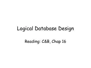
Going to 3NF • REMOVE TRANSITIVE DEPENDENCIES • R1(A, B) – IN 3NF, only one attribute in PK so impossible to have transitive dependency! • R2(C, D, K, E, G, H, I, J) • R3(A, C) • A B, C DK, E GHI, K EJ • C:K is 1:M (C is the many), K:E is 1:M (E is the many) • R2 is replaced by: • R4(C, D, K), R5(K, J), R6(E, G, H, I, K) Logical Database Design (2)
K E D C J I H K B A G K R5 R1 R6 R4 R7 R3 R8 E-R Diagram – 3NF 1 1 M M N M Logical Database Design (2)
Another Example • R(A, B, C, D, E, F, G, H, I, J) • AB -> F G H I J B:AB -> 1:M • B -> C D E AB:H -> M:N • H -> I J • What is the candidate key? • What normal form is this relation in? • Are there any multi-valued attributes? • Are there any partial dependencies? • Are there any transitive dependencies? • Are there any FDs determining part of the CK? Logical Database Design (2)
1NF Anomalies • R(A, B, C, D, E, F, G, H, I, J) • AB -> F G H I J B:AB -> 1:M • B -> C D E AB:H -> M:N • H -> I J • Insertion Anomaly based on Part. Dep.? • Deletion Anomaly based on Part. Dep.? • Modification Anomaly based on Part. Dep.? • To go to 2NF, Decompose Partial Dependencies Logical Database Design (2)
2NF • R1(A, B, F, G, H, I, J) AB:H -> M:N • R2(B, C, D, E) B:AB -> 1:M • AB -> F G H I J, B -> C D E, H -> I J • What are the CKs now? • Are there any foreign keys? Logical Database Design (2)
2NF Anomalies FK • R1(A, B, F, G, H, I, J) AB:H -> M:N • R2(B, C, D, E) B:AB -> 1:M • AB -> F G H I J, B -> C D E, H -> I J • Insertion Anomaly based on Trans. Dep.? • Deletion Anomaly based on Trans. Dep.? • Modification Anomaly based on Trans. Dep.? • To go to 3NF, Decompose Transitive Dependencies Logical Database Design (2)
3NF • R1(A, B, F, G, H, I, J) AB:H -> M:N • R2(B, C, D, E) B:AB -> 1:M • AB -> F G H I J, B -> C D E, H -> I J • Decompose transitive dependencies, R2 is ok • R3(A, B, F, G), R1 is gone! • R4(H, I, J) • R5(A, B, H) • What are the candidate keys now? • What type of relation is R5? Logical Database Design (2)
BCNF • If G -> B then we would decompose further to achieve BCNF Logical Database Design (2)
Could that last example be real? • R(A, B, C, D, E, F, G, H, I, J) • A = Depen. Name • B = Emp. SSN, C D E = Emp. Name, Off, Ph • F G = Depen. Rm#, Ph • H = Depen. Car, I J = car make, model • Each employee can have many dependents, but each dependent has only 1 employee, hence the 1:M between B and AB. • Perhaps siblings share ownership of the car, hence the M:N between AB and H Logical Database Design (2)