Download
1 / 32
390 likes | 631 Vues
Software Receiver Technology. The GALILEO & GPS Software Receiver Company. 30-September-200 4 Tampere University of Technology. NordNav Technologies AB. Unique Competence GPS & GALILEO Real-time Software Receiver Technology Headquarter in Luleå, Sweden Luleå University of Technology

E N D
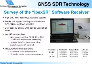
Software Receiver Technology • The GALILEO & GPS Software Receiver Company 30-September-2004 Tampere University of Technology
NordNav Technologies AB • Unique Competence • GPS & GALILEO • Real-time Software Receiver Technology • Headquarter in Luleå, Sweden • Luleå University of Technology • Office in Stockholm • Developing and licensing real-time GPS & GALILEO software receivers
Agenda • GNSS Receiver Technology • Traditional GNSS Receiver Technology • Software Radio Technology • Software GNSS Receiver Technology • Demonstration • NordNav-R30 Software GPS Receiver • New Features • GPS and Galileo • Conclusion
GNSS Receiver – 3 Steps t t Start GPS Start GPS 0 0 • Search phase (acquisition) • Satellite, Carrier Frequency, Code phase • Track satellites (tracking) • Adjust local replica signal using two coupled loops • Code - Delay-Lock-Loop • Carrier - Phase-Lock-Loop • Decode Data message • Navigation computation (navigation) • ”Triangulate” position • Distance to satellites known and their precise position • X,Y,Z, Velocity and Time 0 0 - - 2 2 sec sec Acq Acq t t 1 1 Tracking Tracking 1.2 1.2 - - 6 6 sec sec No No TOW TOW decoded decoded ? ? t t Yes Yes No No 2 2 Ephemeris decoded Ephemeris decoded ? ? 18 18 - - 30 30 sec sec Yes Yes No No 4 4 satellites satellites ? ? Yes Yes Pos Fix t t 3 3
Traditional GNSS Receiver Architecture • Block diagram of a typical GNSS receiver Baseband ASIC Antenna Analog RF Front End ASIC AGC N 2 Digital Receiver Channel 1 Pre Amp(LNA) Down Converter A/D Converter RF Analog IF Digital IF Power Supply Reference Oscillator Frequency Synthesizer Navigation Processing Acquisition Tracking User Interface Low Speed Comm Link Microprocessor
Software Radio • The software radio concept is built upon two basic principles • Move the analog-to-digital converter (ADC) as close to the antenna as possible • Process the resulting samples using a programmable processor Antenna Amplification Analog to digital Conversion (ADC) Analog filtering Programmable element high Available Processing Rate low Microprocessor Microprocessor Microprocessor ASIC FPGA (Assembly (High Level (Simulation Language) Language) Tool) high Level of Flexibility low
Software Radio: Myths & Truths • Current technology simply does not meet the needs for the ”ideal” software radio • High-end analog-to-digital converter (ADC) examples • Maxim MAX104: 8 Bits; 1.0 Gsps; 2.2 GHz Analog Input BW • Analog Devices:AD6645: 14 Bits; 0.105 Gsps; 0.200 GHz Analog Input BW • High performance processor element examples • Intel Pentium IV Processor @ 3.4 GHz clock • Xilinx Virtex II Pro FPGA (up to four embedded PowerPC 405 processors) • Impractical to sample wide spectrum and digitally filter, decimate, and process bands/signals of interest • It is possible to construct multiple front ends and use software to process the output of each • It is possible to have a single front end and use software to provide an efficient, flexible, and dynamic signal processing solution • Such an ”ideal”radio would not be cost-effective
Software GNSS Receiver: Feasibility & Comments • The typical GPS receiver design, with a combination of hardware and software signal processing, is well engineered design • The high speed signal processing deals with a samples on the order of 4-20 Msps, while the low speed programmable processor deals with pre-processed samples on the order of 1 Ksps • Current technology allow for the implementation of a real time GNSS software receiver • Flexible signal processing • Possible to use for new signals and the • Hybrid GPS/Galileo receivers • Potenial low-cost alternative for system integrators • Bandwidth of the signals [sampling frequency] the most important parameter • Moore’s law can be interpreted to show processing power has and continues to increase exponentially since the 1970’s – so tradeoff changes perspective
A Feasible Commercial Software GNSS Receiver Architecture Microprocessor/DSP Antenna Analog RF Front End AGC N 2 Digital Baseband Channel 1 Digital IF Pre Amp(LNA) Down Converter A/D Converter Analog IF Reference Oscillator Frequency Synthesizer Navigation Processing Acquisition Tracking • Downconversion is used – ADC is situated after the IF stage - Ideally programmable bandwidth & frequency band • Signal processing function afterIF stage are realized in software increased flexibility
Two product lines: • PC-based GNSS Receiver : NordNav-Rxx • Specialized customer applications • High end receiver • End customers in R & D • R25/R30 being shipped now! • Embedded Receiver : NordNav-Exx Family • Single point fixes/continuous tracking • Designed for a DSP/Embedded processors • Extremely cost effective (re-use existing processing power in mobile terminal) Automotive General DSP or Microprocessor Mobile Terminals Exx SW NordNav Soft GPS
NordNav-RXX characteristics • Complete receivers targeted towards R&D and Test & Verification market segments • Desktop research • Desktop verification • Specialized customer applications • Designed to run on an PC platform • Multiple sensor integration (GPS/INS/dead reckoning), interference investigations, antenna arrays/beamforming etc. • Record raw IF samples & replay samples
Microprocessor GPS Antenna Data Interface Acqusition Engine Correlator Engine USBv2 IF Samples RF API Acqusition & Tracking Multibit L1 Front End User App. Harddrive Navigation SampleStreamer GUI Receiver GUI NordNav-RXX Architecture
NordNav-R30 Demonstration • Receiver will be run on Pentium 1.7 GHz Notebook PC • Replay a recorded datafile from Stockholm • Unique features briefly demonstrated • 24 channels (typically 14-16 realtime depending on configuration) • Configurable parameters • Add multiple correlators – New feature! • Tracking loop framework – Updated framework • Signal Injection – example study interference effects
Receiver GUI Examples Horizontal scatter plot Monitor the antenna frequency spectrum Monitor AGC level
Real-Time GUI Correlator Plot • Add multiple correlator pairs • Each channel can be individually configured • User can set the tracking pairs & spacing
10 Hz PLL 20 Hz PLL Impact of Tracking Loop Parameters
External Tracking Loop Framework 1(2) • The user can implement its own discriminators for code & carrier • Implement its own code and carrier tracking loop • Excellent for ”aiding” of tracking loops by for example IMU NordNavR30 GUI • Visual C Framework • User implemented code - dll • Example implementation included NordNav R30 API NordNavR30Receiver CloseLoops API CloseLoops.dll
External Tracking Loop Framework 2(2)Updated and added functionality • Updated values every navigation update rate (not every ms as the accumulators): • Satellite positions • Receiver position & velocity • Indicator to tell the receiver to NOT try and extract data • For low C/No studies
Signal Combiner 1(4) • Allows to inject a simulated signal into real GPS samples prior receiver processing • Possibility to study the effect interference signals and jamming scenarios • The user can implement any signal structure, even GPS signals which the receiver can track • Simulated file : each sample stored as signed char (byte)
Signal Combiner 2(4) GPS Signal Stored GPS samples SampleStreamer Multiplicationfactor Antenna R30 SoftwareReceiver Front end A/D Stored external signal samplesExample : Simulated CW, Noise Signal Combiner
Signal Combiner 3(4) >> cw_gen(5e5, 1e6, 0.05, 'cw_500kHz.sim') Included example signal generation scripts CW tonenoise
Signal Combiner 3(4) Example of GPS L1 frequency spectrum with a injected 20 dB CW tone (sinusoid) at 500 KHz off L1 frequency
New features in this software release • Fault Detection and isolation • Improved Dynamic performance • Velocity output • Troposphere (same as WAAS model) • 2-D navigation (height fixing) • Almanac • Configuration per channel basis • Correlators (spacing and numbers) • Tracking loop parameters • Acquisition parameters • External Tracking Loop Framework updated
With Fault Detection Processing – R30 Fault Detection Example (severe multipath reflection) Normal Processing – R30 Reference Receiver Processing
Next Major Software Release • SBAS • Support for WAAS/EGNOS • Scheduled IF recording • Improved Sensitivity • External Position API • Next Next Major Software release • Galileo L1 (software IF signal generator & processing)
Galileo • Galileo – European ”GPS”. Designed to be independent but compatible with GPS • Same frequency band as GPS • Different signal structure • Operational 2008 [2010] • Civil system Great asset for all users with hybrid GPS/Galileo receivers! • Increase service availability drastically! • Five different service categories • Open Service (OS) - Free of charge! • Safety of Life (SoL), Commercial services (CS), Search and Rescue (SAR), Public Regulated Service (PRS)
GNSS Frequency Spectrum Modernized GPS and Glonass signals not included
GPS Signals Carrier at 1575.42 MHz (L1) 1227.60 MHz (L2) 19 cm (L1) Code at 1.023 Mcps (C/A) 10.23 Mcps (P(Y)) 300 m (CA) 6000 km Navigation Data at 50 bps
Galileo BOC(1,1) (data bearing signal) • Code length 8184 chips • 1.023 Mhz base frequency (8 ms period time) • 125 Hz data rate (1 code period per data bit) • ~85 % of signal power within ~4 Mhz bandwidth • GPS C/A • Code length 1023 chips • 1.023 MHz chipping rate (1 ms period time) • 50 Hz data rate (20 code periods per data bit) • ~90 % of signal power within ~2 MHz bandwidth ~4 MHz BW GPS and Galileo Sharing L1 Spectrum : C/A and BOC(1,1)
Conclusion • ”Ideal Software Receiver” is still a dream • Current technology do not allow for such designs • However for bandlimited signals, such as GPS/GNSS, software receiver are commercially feasible • Downconversion front end used • Process digital IF samples in software • Software receivers are receiving market acceptance • Technology not only for research in a laboratory • Although fantastic for this purpose! • More and more feasible as alternative to traditional Rx • Multi-channnel receivers exists today • Important technology for Galileo • Hybrid GPS/Galileo L1 receiver for mass market