Download
1 / 12
150 likes | 492 Vues
Pneumatic Control. Terminology Understanding a P I D controller Valve Positioner and Relays Adjustments and system tuning Mahesh Patil - Chief Engineer Elstan Fernandez - Electrical Officer. Terminology. Desired Value. Controller. Comparator. Transmitter. Open Loop system

E N D
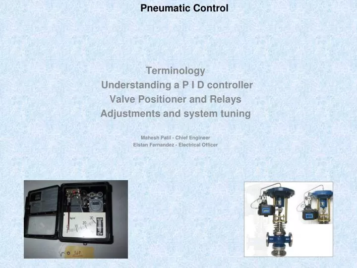
Pneumatic Control Terminology Understanding a P I D controller Valve Positioner and Relays Adjustments and system tuning Mahesh Patil - Chief Engineer Elstan Fernandez - Electrical Officer
Terminology Desired Value Controller Comparator Transmitter • Open Loop system • Closed Loop System • Set Point • Desired Value (DV) • Measured value (MV) • Actual value (AV) • Error (MV - AV) • Deviation (MV - DV) • Offset(Droop) • Comparator • Dead Band • Proportional band • Settling Time Correcting Unit Process Detector Controlled Variable
Types of Control Actions STEP CONTROL • ON – OFF CONTROL SEQUENCIAL CONTROL • PROPORTIONAL CONTROL • P + DERIVATIVE CONTROL • P + INTEGRAL CONTROL • P + I + D CONTROL
Types of Control Actions PROPORTIONAL - (m)controller o/p is proportional to deviation { e(t)} m = - Kp * e(t) INTEGRAL - Rate of change of (m)controller o/p is proportional to deviation { e(t)} dm / dt = Ki * e(t) i.e m = - Ki ∫ e(t) * dt DERIVATIVE - (m)Controller o/p is proportional to rate of change of deviation { e(t)} m = - Kd * de(t) / dt
Nozzle – Flapper Arrangement • Acts as a transducer or an signal amplifier • Supply Air Pr – 1.5 bar • Control air output pr range -- 3 ~ 15 psi • Flapper Movement(X1, X2) approx 20 microns • Orifice Dia – 0.25 mm • Nozzle Dia – 0.40 mm
Nozzle – Flapper Arrangement in a PID Controller (Rate adjustment) (Reset Time)
Nozzle – Flapper Arrangement in a Valve Positioner Valve Positioner See how it works Foxboro’s Different Positioners
Vigilance and Maintenance Periodic calibration and cleaning of measuring devices/sensors (e.g. RTD probe in the FO purifier heater line, M/E JCW line etc.) Replacement of polyurethane tubes inside the controller every 24 months, as tubes tend to damage due to heat, oil and vibration. Quarterly cleaning of nozzle with a thin SS wire (<0.25 mm) Weekly cleaning of orifice by depressing the push button. Bellows and linkages must be checked for their intactness. Watch out for signs of air leakages inside the controller box Leakages in signal transmission lines from controller to regulating valve. Condition and integrity of valve packing/seals, moving surface of valve spindles. And Most important, cleanliness of supply air. Correct working of filters and Pressure reducers.