Download
1 / 47
470 likes | 608 Vues
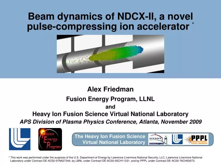
Beam dynamics of NDCX-II, a novel pulse-compressing ion accelerator *. Alex Friedman Fusion Energy Program, LLNL and Heavy Ion Fusion Science Virtual National Laboratory APS Division of Plasma Physics Conference, Atlanta, November 2009.

E N D
Beam dynamics of NDCX-II, a novel pulse-compressing ion accelerator * Alex Friedman Fusion Energy Program, LLNL and Heavy Ion Fusion Science Virtual National Laboratory APS Division of Plasma Physics Conference, Atlanta, November 2009 The Heavy Ion Fusion Science Virtual National Laboratory * This work was performed under the auspices of the U.S. Department of Energy by Lawrence Livermore National Security, LLC, Lawrence Livermore National Laboratory under Contract DE-AC52-07NA27344, by LBNL under Contract DE-AC02-05CH11231, and by PPPL under Contract DE-AC02-76CH03073.
This work was done in collaboration with others … LLNL: John Barnard, Ron Cohen, Dave Grote, Steve Lund, Bill Sharp LBNL: Andy Faltens, Enrique Henestroza, Jin-Young Jung, Joe Kwan, Ed Lee, Matthaeus Leitner, Grant Logan, Jean-Luc Vay, Will Waldron PPPL: Ron Davidson, Mikhail Dorf, Phil Efthimion, Erik Gilson, Igor Kaganovich
Outline Introduction to the project 1-D ASP code model and physics design Warp (R,Z) simulations 3-D effects: misalignments & corkscrew Status of the design
DOE’s Office of Fusion Energy Sciences approved the NDCX-II project earlier this year. $11 M of funding has been provided via the American Recovery and Reinvestment Act (“stimulus package”). NDCX-II is under way ! Construction of the initial 15-cell configuration began in July 2009, with completion planned for March 2012.
NDCX-II will enable studies of warm dense matter, and key physics for ion direct drive LITHIUM ION BEAM BUNCH (ultimate goals) Final beam energy: ~ 3 MeV Final spot diameter : ~ 1 mm Final bunch length : ~ 1 cm or ~ 1 ns Total charge delivered: ~ 30 nC TARGET mm foil or foam Exiting beam available for measurement 30 J/cm2 isochoric heating would bring aluminum to ~ 1 eV
“Neutralized Drift Compression” produces a short pulse of ions The process is analogous to “chirped pulse amplification” in lasers A head-to-tail velocity gradient (“tilt”) is imparted to the beam by one or more induction cells This causes the beam to shorten as it moves down the beam line: vz z (beam frame) vz z (beam frame) • Space charge would inhibit this compression, so the beam is directed through a plasma which affords neutralization • Simulations and theory (Voss Scientific, PPPL) showed that the plasma density must exceed the beam density for this to work well
NDCX-I at LBNL routinely achieves current and power amplifications exceeding 50x beam transport solenoids induction bunching module drift compression line final focus solenoid injector target chamber with plasma sources NDCX-I
LLNL has given the HIFS-VNL 48 induction cells from the ATA • They provide short, high-voltage accelerating pulses • Ferrite core: 1.4 x 10⁻³ Volt-seconds • Blumlein: 200-250 kV; 70 ns FWHM • At front end, longer pulses need custom voltage sources; < 100 kV for cost Advanced Test Accelerator (ATA) Test stand at LBNL
NDCX-II(23-cell design) water-filled Blumlein voltage sources Li+ ion injector oil-filled transmission lines ATA induction cells with pulsed 1-3T solenoids Length ~ 15 m Avg. 0.25 MV/m Peak 0.75 MV/m neutralized drift compression line with plasma sources final focus and target chamber
Outline Introduction to the project 1-D ASP code model and physics design Warp (R,Z) simulations 3-D effects: misalignments & corkscrew Status of the design
1-D PIC code ASP (“Acceleration Schedule Program”) Follows (z,vz) phase space using a few hundred particles (“slices”) Accumulates line charge density l(z) on a grid via particle-in-cell Space-charge field via Poisson equation with finite-radius correction term Here, α is between 0 (incompressible beam) and ½ (constant radius beam) Acceleration gaps with longitudinally-extended fringing field Idealized waveforms Circuit models including passive elements in “comp boxes” Measured waveforms Centroid tracking for studying misalignment effects, steering Optimization loops for waveforms & timings, dipole strengths (steering) Interactive (Python language with Fortran for intensive parts)
Physics design principle 1: Shorten Beam First (“non-neutral drift compression”) Equalize beam energy after injection -- then -- Compress longitudinally before main acceleration Want < 70 ns transit time through gap (with fringe field) as soon as possible ==> can then use 200-kV pulses from ATA Blumleins Compress carefully to minimize effects of space charge Seek to achieve large velocity “tilt” vz(z) ~ linear in z “right away”
Physics design principle 2: Let It Bounce Rapid inward motion in beam frame is required to get below 70 ns Space charge ultimately inhibits this compression However, so short a beam is not sustainable Fields to control it can’t be “shaped” on that timescale The beam “bounces” and starts to lengthen Fortunately, the beam still takes < 70 ns because it is now moving faster We allow it to lengthen while applying: additional acceleration via flat pulses confinement via ramped (“triangular”) pulses The final few gaps apply the “exit tilt” needed for neutralized drift compression
Pulse length vs. z: the “bounce” is evident pulse length (m) center of mass z position (m)
Pulse duration vs. z - time for entire beam to cross a plane at fixed z * time for a single particle at meanenergy to cross finite-length gap + time for entire beam to crossfinite-length gap pulse duration (ns) center of mass z position (m)
Voltage waveforms for all gaps “flat-top” (here idealized) “ramp” (using measured waveform from test stand) “shaped” (to impose velocity tilt for initial compression) gap voltage (kV) equalize beam energy after injection time (µs)
A series of snapshots from ASP shows the evolution of the (kinetic energy, z) phase space and current profile
Outline Introduction to the project 1-D ASP code model and physics design Warp (R,Z) simulations 3-D effects: misalignments & corkscrew Status of the design
Design of injector is done using Warp PIC code in (r,z) geometry First, use Warp’s steady-flow “gun” mode: emitter 130 kV extractor 111 kV accel -50 kV decel 0 V (during main pulse) 0 R (m) 0.1 10 cm 0 0 Z (m) 1 For full runs, use time-dependent space-charge-limited emission and simple mesh refinement (2 mA/cm2 Li+ emission)
Outline Introduction to the project 1-D ASP code model and physics design Warp (R,Z) simulations 3-D effects: misalignments & corkscrew Status of the design
Video: Warp 3-D simulation of NDCX-II beam (no misalignments)
Video: Warp 3D simulation of NDCX-II, including random offsets of solenoid ends by up to 1 mm (0.5 mm is nominal)
ASP employs a tuning algorithm (as in ETA-II, DARHT)† to adjust “steering” dipoles so as to minimize a penalty function Trajectories of head, mid, tail particles, and corkscrew amplitude, for a typical ASP run. Random offsets of solenoid ends up to 1 mm were assumed; the effect is linear. Dipoles in every 4th solenoid; optimization penalizes corkscrew amplitude & beam offset, and limits dipole strength Dipoles off x - solid y - dashed Corkscrew amplitude - black Head - red Mid - green Tail – blue †Y-J. Chen, Nucl. Instr. and Meth. A 398, 139 (1997).
Outline Introduction to the project 1-D ASP code model and physics design Warp (R,Z) simulations 3-D effects: misalignments & corkscrew Status of the design
The “physics design” is periodically updated, using several steps • Use Warp to develop the diode and injector • Capture particle data at a plane upstream of the first gap, import into ASP • Run ASP; optimize the machine “lattice” (drift spaces) & gap waveforms • Import lattice and waveforms into Warp, and in (r,z) geometry: • optimize solenoid strengths for a transversely “well-matched” beam • optimize final focusing solenoid for a small spot, with focal plane coincident with shortest pulse duration • Using the above solenoid strengths, use ASP to study beam steering • Using Warp in 3-D, assess effects of misalignments on focal intensity • Coming up: comprehensive simulations including all non-ideal effects, coupled with steering and other corrections In some ways the process is analogous to fusion target design: we use simulations to develop shaped impulses that yield a desired compression
NDCX-II beam neutralization is based on NDCX-I experience Ferroelectric Plasma Source Developed by PPPL Cathodic-Arc Plasma Source
Key technical issues are being addressed Li+ ion source current density We have measured* 3 mA/cm2, but for NDCX-II assume 1 - 2 mA/cm2 Pulsed solenoid effects Volt-seconds of ferrite cores are reduced by return flux of solenoids Eddy currents (mainly in end plates) dissipate energy, induce noise We’ll use flux-channeling copper shells, and thinner end plates Solenoid misalignment effects Steering reduces corkscrew but requires beam position measurement If capacitive or magnetic BPM’s prove too noisy, we’ll use scintillators or apertures Require “real” voltage waveforms A good “ramp” has been measured, and is used in ASP and Warp runs We’re developing shaping circuits for “flatter flat-tops”; will revise design to use the measured waveform *P. K. Roy, et al., paper B06.00014, presented earlier today
We look forward to a novel and flexible research platform NDCX-II will be a unique ion-driven user facility for warm dense matter and IFE target physics studies. The machine will also allow beam dynamics experiments relevant to high-current fusion drivers. The baseline physics design makes efficient use of the ATA components through rapid beam compression and acceleration.
Later in this meeting … presentations on the physics of ion beams warm dense matter HIF targets Poster Session NP8, Wednesday, 9:30 AM in Grand Hall East 2 and 3: NDCX-I results 4, 5, and 110: NDCX-II studies 6 – 9: ion beam dynamics (neutral and non-neutral) 93 – 96: WDM and HIF targets Oral Session T05, Thursday, 9:30 AM in Hanover CDE 2 (9:42 AM): John Perkins, “High gain high efficiency heavy-ion direct drive targets”
A simple passive circuit can generate a wide variety of waveforms Waveforms generated for various component values: charged line ATA “compen-sation box” induction cell & accelerating gap impedance
Passive circuit elements inserted into “compensation boxes” attached to the induction cells can shape waveforms nicely Nearly linear voltage ramp over ~ 60 ns
The field model in ASP yields the correct long-wavelength limit For hard-edged beam of radius rb in pipe of radius rw , 1-D (radial) Poisson eqn gives: The axial electric field within the beam is: For a space-charge-dominated beam in a uniform transport line, l/rb2 ≈ const.; find: For an emittance-dominated beam rb ≈ const.; average over beam cross-section, find: The ASP field equation limits to such a “g-factor” model when the k⊥2 term dominates In NDCX-II we have a space-charge-dominated beam, but we adjust the solenoid strengths to keep rb more nearly constant; In practice we tune α to obtain agreement with Warp results
Warp • 3-D and axisymmetric (r,z) models • Electrostatic space charge and acceleration gap fields • Time-dependent space-charge-limited emission • Cut cells boundaries, AMR, large-timestep drift-Lorentz mover, … • Interactive (Python language) • Extensively benchmarked against experiments & analytic cases
A series of snapshots from ASP shows the evolution of the (velocity, z) phase space and line charge density profile
ASP simulation of NDCX-II with 0.5 mm random magnet offsets and tilts shows that the beam reaches the target without steering Should pass acceptance test without any steering. For operation, “Tuning V” methods from ATA, DARHT will be used.
Warp 3D simulations indicate slow degradation of the focus as misalignment of the solenoids increases Random offsets in x and y were imparted to the solenoid ends. The offsets were chosen from a uniform distribution with a set maximum. Energy deposited within 1 mm Peak deposition of the location of the peak
“Tuning V” algorithm (modeled in ASP) adjusts “steering” dipole currents so as to minimize a penalty function at the next sensor x,y vs z trajectories of head, mid, tail particles and the corkscrew size for a typical ASP run Simple tuning-V reduces corkscrew but still has a large centroid error Before optimization x - solid y - dashed Head - red Mid - green Tail – blue Corkscrew - black Random offsets of solenoid ends up to 1 mm were assumed; the effect is linear.
Beam offset can be added to penalty, but care is needed Resonance occurs between sensor spacing and centroid oscillation Constraining the dipole strength to< 100 Gauss reduces the peak Head - red Mid - green Tail – blue Corkscrew - black x - solid y - dashed
An ensemble of runs shows the same trends x,y vs z trajectories of head, mid, tail particles and the corkscrew amplitude Before optimization Head - red Mid - green Tail – blue Corkscrew - black x - solid Simple tuning-V algorithm reduces the corkscrew amplitude but does not reduce the centroid error y - dashed The results are averages over 20 simulations with differing random offsets of solenoid ends up to 1 mm.
The effects of penalizing the beam offset and dipole strength are clearer when an ensemble of runs is examined Resonance between sensor spacing and cyclotron oscillation spatial period Constraining the dipole strength to< 100 Gauss removes the peak Head - red Mid - green Tail – blue Corkscrew - black x - solid y - dashed
Fluence at target plane is appropriate for WDM experiments 34-cell lattice produces 4.3-MeV beam with final radius less than 1 mm • emittance remains between 1-2 mm-mrad through lattice • radius fluctuates between 2-3 cm during acceleration
NDCX-II represents a significant upgrade over NDCX-I Baseline for WDM experiments: 1-ns Li+ pulse (~ 2x10¹¹ ions, 30 nC, 30 A) For experiments relevant to ion direct drive: require a longer pulse with a “ramped” kinetic energy, or a double pulse.