Download
1 / 14
140 likes | 274 Vues
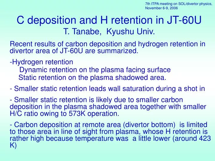
7th ITPA meeting on SOL/divertor physics, November 6-9, 2006. C deposition and H retention in JT-60U T. Tanabe, Kyushu Univ. Recent results of carbon deposition and hydrogen retention in divertor area of JT-60U are summarized. Hydrogen retention Dynamic retention on the plasma facing surface

E N D
7th ITPA meeting on SOL/divertor physics, November 6-9, 2006 C deposition and H retention in JT-60UT. Tanabe, Kyushu Univ. Recent results of carbon deposition and hydrogen retention in divertor area of JT-60U are summarized. Hydrogen retention Dynamic retention on the plasma facing surface Static retention on the plasma shadowed area. - Smaller static retention leads wall saturation during a shot in - Smaller static retention is likely due to smaller carbon deposition in the plasma shadowed area together with smaller H/C ratio owing to 573K operation. - Carbon deposition at remote area (divertor bottom) is limited to those area in line of sight from plasma, whose H retention is rather high because temperature was a little lower (around 423 K)
= 0 When Wall saturates 3 ∽ 6 1020 Only for plasma facing area
Twall = 420 K Twall = 520 K Hydrogen wall saturation does appear in JT-60U Wall saturation → tritium inventory also saturates → lead to poor plasma confinement Nakano et al. 16th PSI
It is critically important whether hydrogen retention saturates or not. Static retention : incorporated in redeposited carbon layers at plasma shadowed area Dynamic retention : retained in plasma facing surface area both eroded and deposited Takenaga et al. J. Nuclear Fusion,46 (2006) S39-S48 Which is large, Static or Dynamic? In Tore-Supra; Static >> Dynamic and ∂S/∂t > ∂D/∂t In JT-60U ; Static > Dynamic but ∂S/∂t < ∂D/∂t
Erosion deposition summary Samples: 1997~1999 (outer dome wing :1999) Y.Gotoh et al. J. Nucl. Mater, 357(2006)138-146
JT-60U H+D retention in divertor area : Summary I Except the side facing to the pumping duct, H+D retention on tile sides is less than that on the plasma facing sides. Y. Hirohata et al. 17th PSI
(d) (b) e-folding length: 3mm (a) (c) e-folding length: 3mm (a) (b) (c) (d) e-folding length: 3mm e-folding length: 3mm In tile gaps, tritium was retained in redepoited carbon, showing two decay components, the main component caused by ionic species with minor contribution of neutral origin with longer decay. • DV-b: Inner target tile • DM-a: Dome inner wing tile • DM-c: Dome outer wing tile • DV-d: Outer target tile
50µm Deposition (g) 100µm e-folding length: 3 mm Gap facing outer pumping slots has heavy deposition Large ionic contributionsimilar to toroidal sides (a) (a) (d) e-folding length: 7 mm Inner divertor (d) (a) JT-60U (f) (g) (f)
JT-60U H+D retention in divertor area : Summary II Most of D retained in plasma facing surface was replaced by H D/H ratio Y. Hirohata et al. 17th PSI
Carbon deposition and H+D+T retention at remote area NB injection time : 8 x 10³ s Average deposition thickness : ~2µm Estimated density : ~1.8 g/cm3 Area : 3.8 m2 Total deposition : ~0.013 kg (~8 x 10¹⁹ C/s) Baking temperature : ~420 K K.Masaki et al. IAEA 2006
JT-60U H+ D retention Summary Baking temperature : ~420 K
Summary - I • Hydrogen retention in tokamak could be devided into two components, i.e. dynamic retention on the plasma facing area and static retention at the tile gaps and remote area. • Dynamic retention saturates (at higher the surface temperature, more easily it saturates) and is always replaced by new impinging hydrogen. Therefore a few DD discharges after large numbers of DT discharges could significantly reduce T retention on the plasma facing surface. • Static retention will not saturates but changes significantly depending on machine conditions and geometry of tiles and divertor structure.
Summary - II • Static retention on tile gaps might not be large and divided into two components. One is incorporated in carbon redeposited layers produced by prompt redeposition of carbon eroded at plasma facing surface, and the other is in the carbon layers produced penetrated neutrals in the gap. Hence, narrowing the tile gap, the carbon deposition could be reduced. • A far remote area in JT-60U divertor, carbon redeposition is hardly observed. The reason is not clear. Since there is no evidence for large amount of hydrocarbon exhaust, production of hydrocarbons in JT-60U could be less than other large machine.