Download
1 / 33
330 likes | 445 Vues
Proton Polarimetry at the Relativistic Heavy Ion Collider and Future Upgrades. Yousef I. Makdisi Brookhaven National Laboratory For The RHIC Polarimetry Group I. Alekseev, E. Aschenauer, G. Atoian, A. Bazilevsky, A. Dion, H. Huang,

E N D
Proton Polarimetry at the Relativistic Heavy Ion Collider and Future Upgrades Yousef I. Makdisi Brookhaven National Laboratory For The RHIC Polarimetry Group I. Alekseev, E. Aschenauer, G. Atoian, A. Bazilevsky, A. Dion, H. Huang, A. Poblaguev, W. Schmidke, D. Smirnov, D. Svirida, K. Yip, A. Zelenski * Run 11 analyses: Dion, Poblaguev, Schmidke, Smirnov
Outline • Requirements for the physics program and machine development • The p-Carbon CNI polarimeters and Jet for Run 11 • The operation in Run 11 • The p-C polarimeters • The Polarized Jet target • The Results • The path forward
The Polarimetry Requirements for RHIC • The polarimeters should operate over a very wide range, with beam energy ranging from injection at 24 to 250 GeV • The physics program requires precision polarimetry < 5% • Polarimeter calibration is required at each energy • Beam polarization profile(s) • Polarization lifetime or decay during a store • Polarization measurement on the ramp • Bunch to bunch emittance measurements
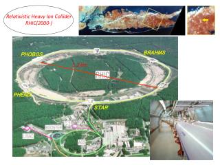
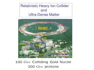
The RHIC Polarized Collider RHIC pC Polarimeters Absolute Polarimeter (H jet) ANDY E-Lens and Spin Flipper Siberian Snakes Siberian Snakes PHENIX STAR Spin Rotators (longitudinal polarization) Spin Rotators (longitudinal polarization) Pol. H- Source LINAC EBIS BOOSTER Helical Partial Siberian Snake AGS 200 MeV Polarimeter AGS pC Polarimeter Strong AGS Snake
pp and p-Carbon Elastic Scattering elastic kinematics are fully constrained by the recoils only ! 0.001 < |t| < 0.02 (GeV/c)2 scattered proton polarized p beam recoil proton or carbon recoil p For p-p elastic scattering only:
RHIC Polarimeters Layout • Two polarimeters in each beam (redundancy) • A pair of polarimeters readout inside the tunnel (an • attempt to reduce dispersion through the long 70m cables) • After tests in the AGS replaced charge sensitive • amplifiers with fast current sensitive amplifiers for all • Target holders 6 (V) 6 (H) in each polarimeter • Simultaneous H and V pol. Profiles • In situ test of new detectors • New 1 mm Hamamatsu detectors • Multiplexing to reduce cost
Detector port (inner view) SSD p-Carbon Polarimeters Energy Calibration Ultra thin Carbon ribbon Target (5mg/cm2) Fitting Error < 0.01% 6 1 • Alpha source • 5.486 MeV (85%) • 5.443 MeV (12%) 2 5 E ADC [ch] 3 4 ~50keV/ch 2mm pitch 12 strips 10mm
L Target (effective dead layer) (adcC) Energy Correction (t0,x)Kinematic Fit Run5: 40-55 g/cm2 Run6: 70-80 g/cm2 Run8: 75-90 g/cm2 Run9: 50-80 g/cm2 Run 11: 60-65g/cm2 10 g/cm2 6% in AN
Online Polarimeter display Carbon rate 50 - 100 kHz/ strip Prompts background to signal ~ 1/1 with an energy threshold cut at 125 keV. Shaper pulse rise time 20 nsec and fall time 50 nsec
2. Obtain R directly from the P(I) fit: I P pC: Polarization Profile 1. Directly measure I and P : pC Scan the Carbon target over the beam: Intensity I Polarization P R=0.290.07 Target Position Precise target positioning is NOT necessary R ~ 0.1–0.3 5–15% difference in lower polarization seen by HJet compared to that observed by experiments
The Polarized H-Jet Target H2 dissociator RF cavity H = p++e- separation magnets (sextupoles) Atomic Beam Source focusing magnets (sextupoles) OR RF transitions Scattering chamber Holding field magnet P+ OR P- record beam intensity 100% eff. RF transitions focusing high intensity B-R polarimeter Ptarget ~ 0.924 ± 0.018 recoil detectors ToF, EREC; QREC Breit-Rabi Polarimeter Ion Gage
Ch#14 Ch#3 Ch#4 Ch#6 Ch#15 Ch#9 Ch#7 Ch#8 Ch#10 Ch#13 Ch#16 Ch#5 Ch#11,12 Ch#2 Ch#1 Ch#1-16 • source for energy calibration • 241Am(5.486 MeV) R Recoil Spectrometer MeasurementH. Okada Forward scattered proton proton beam proton target recoil proton #16 Ch#1 Array of Si detectors measures TR & tof of recoil particles. Channel # corresponds to recoil angle R. 2 correlations (TR & tof ) and (TR & R ) the elastic process
Operational Problems Run 11 • Jet: • The Jet had a mishap early in the run where enough dissociator RF power was dumped to cause significant damage to the nozzle • Since, were not able to run the intensity at the prescribed pattern, namely high to start and slowly depletes over the period of two weeks. Instead we reverted to more frequent nozzle cleaning (more downtime) • We also lost our usual number of turbo pumps • Polarimeters: • The idea of running the downstream polarimeters readout inside the tunnel did not work as we faced frequent downtime to what appears as single event upset to the electronics. No long term radiation damage was seen as the equipment was moved outside • We did experience unusual target losses in one polarimeter which was attributed to one mechanical drive
Running conditions Run 11 • Ran with two beam simultaneously separated • vertically by 3-4 mm dictated by the machine • beam-beam requirements • Backgrounds were minimal no grater than one • Beam condition • Simultaneously measured AN in pp elastic • Scattering at the specified energy and beam • Polarization • Ran at both 250 GeV and injection 24 GeV
Results Run 11 • Measured the Analyzing Power in pp elastic • scattering to assure all is fine • Used the average AN to normalize the beam • asymmetry for each fill. • Note the jet beam is 6 mm FWHM sees the full • beam profile • Averaged over the Run: • Blue Beam Polarization ~ 48% • Yellow Beam Polarization ~ 48% • 2011 • 2009
Results Run 11 (Jet contamination??) • A Recoil Energy Cut to test for pion • contamination or dilution if any: • At 5 MeV (nominal) • Blue : 0.480 +/- .0053 • Yellow: 0.479 +/- 0053 • At 4 MeV • Blue : 0.484 +/- .0056 • Yellow : 0.482 +/- .0057 • At 3 MeV • Blue: 0.486 +/- .0064 • Yellow : 0.476 +/- .0066 pp elastic p, p+mπ p,p+2mπ
Results RUN 11 Polarimeters (Cont’d) 24 GeV 250 GeV
Results Run 11 (Cont’d) Longitudinal Profiles (Jet data 2 nsec bins) Polarization Polarization Loss over the fill (Jet data)
Polarized Hjet: AN Used for polarization measurements pp-CNI Weak (if any) energy dependence pp elastic scattering in CNI region is ideal for polarimetry in wide beam energy range 24 GeV: PRD 79, 094014(2009) 31 GeV: Preliminary 100 GeV: PLB 638 (2006) 450 250 GeV: Preliminary Possibly an unpolarized hydrogen Jet for higher intensity?
p-Carbon: AN Used for polarization measurements pC-CNI 31 GeV 100 GeV 250 GeV Weak energy dependence pC elastic scattering in CNI region is good for polarimetry in wide beam energy range 10% normalization uncertainty not included Point-to-point syst. uncertainty under study
A Path Forward (polarimeters) • With the rate dependence issues solved. We look towards more stability and reliability of our operational stability • Complete analysis of the 1 mm Hamamatsu strip detectors • We also have 1 mm BNL fabricated silicon and will assess suitability • Smaller acceptance per strip to ameliorate the rate issues as the accelerator strives to higher bunch intensities • Look into commercial WFD systems • Stream line and speed up the DAQ system, reduce the impact on the experiments • Continue to improve target production QA • Better Slow Controls, calibration, and monitoring • Utilize scintillation counters to get a handle on T0 • and dead layer evaluation • Add Gadolinium sources 3.27 MeV alpha, better energy calibration
A Path Forward (Jet Target) • Install Hamamatsu 300 (3mmx30mmx16) Silicon Photodiode PIN detectors on two of the six Jet detectors • Use the same amplifier / shaper and WFD readout • In situ comparison with the current Hamamatsu Jet detectors: • Energy resolution and thus lower t reach • Susceptibility to beam induced background • Evaluate any difference in radiation damage • Longer Term redesign the Jet detector flanges to increase the acceptance by a factor of 2 • Need a better handle on the Jet systematics. 45x50mm, 4x12=48 strips (4mm by 50+50=100mm)
Summary • A new RHIC polarimetry group is on board and had a busy year • The AGS rate studies resulted in installation of current sensitive amplifiers in the RHIC polarimeters and resolved the rate problem for now. No significant increase in noise either. • We experienced a more stable running environment • The readout inside the RHIC tunnel did not pan out due to disruption from possible single event upset problems >> reverted to the out side • Complementary local polarimeters are employed at the experiments ZDC (inclusive neutron asymmetry) and beam – beam counter types) • Towards He3 polarimetry a Workshop at BNL Sept 28-30, 2011
Rate Studies Atoian, Bazilevsky, Gill, Morozov, Rescia • We have in hand several data runs with high rate and the nominal WFD readout • We have taken special measurements to study rate problems varying: • The beam intensity and number of bunches • The polarimeter target thickness • With help from the Instrumentation Division also used a fast scope (20 G samples/sec) to study the pulse height and baseline variation versus rate at the output of various stages: • The preamplifier • The shaper • With BNL and Hamamatsu detectors • With the Yale WFD readout in a full waveform mode to study baseline shifts • With a separate ADC and TDC readout • Analyses are ongoing but seem to indicate that both the BNL and Hamamtsu detectors can handle the high rates through the shaper stage.
Polarimeters problems C-rate Pulser rate Pulser amp. Pulser time
Resonance around 138 GeV Polarization On The Ramp Two such examples: For the AGS where we sum over Many passes to accumulate statistics In this case ramped up and down For RHIC @ 250 GeV ramp were each is a single pass limited by the onboard local memory preliminary
2005 Jet Normalization Summary • Blue • Yellow A_N(2005) = A_N(2004) x (S +/- DA(jet stat)/A +/- DA(jet syst)/A +/- DA(pC syst)/A) A_N(05)=A_N(04)x( 1.01 +/- .031 +/- .029 +/- .005) DP/P(profile)=4.0% DP(blue)/P(blue) = 5.9% A_N(05)=A_N(04)x( 1.02 +/- .028 +/- .029 +/- .022) DP/P(profile)=4.1% DP(yellow)/P(yellow) = 6.2% Goal: 10% D[P(blue) x P(yellow) ]/[P_b x P_y] = 9.4%
APEX Rate Studies Injected Generator pulse No target With a thin Carbon target Carbon rate 42 kHz/ strip With a thick target Carbon rate 157 kHz/strip No appreciable change observed
Rate dependence for 0.6 MeV C: For comparison rate at RHIC 50-100 kHz/ strip
New Detector Tests Atoian, Gill, Morozov • Compare BNL and Hamamatsu large area (1cm x 1cm) Si and strip PIN photodiode detectors. Results show a several advantages to use these devices instead of the strip detectors • A factor of ~2 better resolution (21 KeV vs. 43 KeV) which allows us to measure elastic carbons at ~ t=-0.005 GeV/c2 at higher analyzing power • ~ 20 times less bias current after 4 months working on the RHIC beam (0.23A vs. 4 A) • Simplify the readout electronics as well as DAQ