Download
1 / 8
80 likes | 220 Vues
Treatment of Grating Pairs Using Plane-Wave Approximation LIGO-G040194-00-Z. Yanbei Chen based on Talks of Stacy Wise and Volker Quetschke E.B. Treacy, IEEE J. of Quant Elec, 9, QE-5 (1969)] Discussions made at the configuration sessions. Single grating, single plane wave. Incident wave

E N D
Treatment of Grating Pairs Using Plane-Wave ApproximationLIGO-G040194-00-Z Yanbei Chen based on Talks of Stacy Wise and Volker Quetschke E.B. Treacy, IEEE J. of Quant Elec, 9, QE-5 (1969)] Discussions made at the configuration sessions
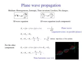
Single grating, single plane wave • Incident wave • On the surface (ingoing wave) • Immediately after (outgoing wave) Outgoing waves We only consider one of the non-zero orders!
A Pair of Gratings: I • At the surface of the second grating • Immediately after second grating • Final outgoing wave 8. Phase of the outgoing plane wave:
A Pair of Gratings: II From geometry, this is indeed
What`s wrong with our previous understanding? • The grating is not simply reflecting the plane wave, but instead imposes an x-dependent phaseshift. • At first sight, this phaseshift is oscillatory, i.e. 2h(x ) in page 2. But for any particular diffraction order, this phase shift is linear (nax ) in x! • As a consequence, we can effectively think of the grating pair as a pair of mirrors with frequency dependent orientation [see Treacy`s first derivation] --- this is why our original thought was completely wrong.
Treacy`s second derivation: I • Consider a trial impulse with frequency spectrum A(w) , centered at w0 . If, at the output port of the two-grating system, • Then the Stationary-Phase Approximation implies a pulse delay of • Interestingly, this shows that, for plane waves and assuming no amplitude modulation, the white-light effect should not exist! • Now, back to our grating system, can we actually show that t=L(w)?
Treacy`s second derivation: II • Now suppose we have an impulse at the input port (with various values of k) • Pulse peak trajectory, before hitting the grating, is given by (SPA) • After the grating, k-component will be diffracted to k’ • The peak trajectory is given by (SPA again) • The pulse travels along k’ with speed c:same direction and speed as the phase front!! Travel times is t=L(w)!
Summary • A grating pair can be analyzed qualitatively by elementary scalar-wave optics, yielding / =L()/c, which, being always positive, is fundamentally different from our old understanding of = L() /c. • Two methods can be used to analyze the grating-pair system, as given by Treacy: • When using monochromatic plane waves, one has to be careful about defining the planes of reflection: they are not parallel to the grating surfaces![Origin of our long-time mistake.] • One can also inject pulses into the grating system as gedanken experiments. • One has a pulse delay of t= /. This already means that white-light cavity cannot be made. • For a grating pair, the pulse travels in the same way as the phase front, so t= L()