Download
1 / 13
130 likes | 284 Vues
Data Link Layer – Part 1. V.T.Raja Oregon State University. Data Link Layer – Part 1. Introduction Data link layer is between the _______ layer and the __________ layer Examples of data link layer protocols: Most data link protocols perform three major functions.

E N D
Data Link Layer – Part 1 V.T.Raja Oregon State University
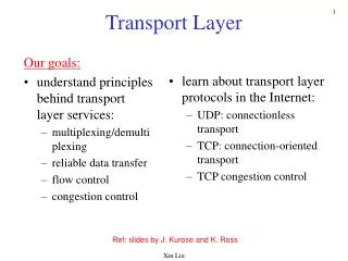
Data Link Layer – Part 1 Introduction • Data link layer is between the _______ layer and the __________ layer • Examples of data link layer protocols: • Most data link protocols perform three major functions
Media Access Control • When is MAC important? • Data flow • Simplex (One-way transmission) • Half-duplex (Two-way transmission, but only one direction at a given time) • Full-duplex (Two-way transmission simultaneously)
Controlled Access Polling Roll call polling Frequent roll call ‘Time-out period’ Hub polling Token passing Contention Computers wait until the circuit is free (i.e., no other computers are transmitting) Example: Which is better – Contention or Controlled Access? MAC Types
Network Errors • Errors are not uniformly distributed, regardless of error rate statistics (e.g., Error rate: 1 in 500,000; 100 in every 50 million bits) • Normally errors occur in bursts Burst errors • Two categories of network errors • Corrupted data (that have been changed) • Lost data
Source of error Line outages White noise Impulse noise Cross-talk Attenuation What Causes it? Storms, Accidents Static (Movement of electrons) Sudden increase in electricity; voltage fluctuations MUX guardbands too small Decrease in signal power over distance Sources/causes of network errors
Error Detection • It is possible to develop data transmission methodologies that vibe very high error detection and correction performance. • The only way to do error detection and correction is to send extra data with each message. • In general, the larger the amount of error detection data sent, the greater the ability to detect an error. • Efficiency of data throughput varies inversely as the desired amount of error detection is increased.
Error Detection Techniques • There are three common error detection methods. • Parity Checking • Even Parity • Odd Parity • Longitudinal Redundancy Checking (LRC) • Polynomial Checking • Checksum • Cyclic Redundancy
Parity Checking • One of the oldest and simplest method, parity checking adds 1 additional bit to each byte in the message. The value of this parity bit is dependent on the number of 1’s in each byte transmitted. The parity bit is set to make the total number of 1’s in the byte (including the parity bit) either an even number (even parity) or an odd number (odd parity). • Examples • Does parity checking work if two bits are erroneous?
Longitudinal Redundancy Checking (LRC) • LRC was developed to overcome the problem with parity’s low probability of detection. • LRC adds one additional character, called the block check character (BCC) to the end of the entire message or packet of data. • The value of the BCC is calculated much like the Parity bit, but for the entire message. Results in a 98% reliability rate. • Example
Polynomial Checking • Like LRC, polynomial checking adds 1 or more characters to the end of the message based on a mathematical algorithm. • With checksum, 1 byte is added to the end of the message. It is obtained by summing the message values,and dividing by 255. The remainder is the checksum. (95% effective) • With CRC, 8, 16, 24 or 32 bits are added, computed by calculating a remainder to a division problem. (99.969% with 8-bit, 99.99% with 16 bit).