Download
1 / 15
150 likes | 257 Vues
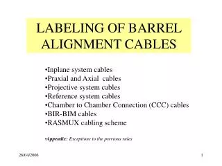
K. Gabathuler March 2005. PIXEL CABLING ISSUES General Optical Cables Copper Cables ( Power & Control ) Things to be done. PP1. PP0. USC55. Service Tube. Gallery. ~ 4-5 m. 0.6m. ~ 40 m. ~ 40 m. Optical Cabling and Patch Panels M eeting with F. Vasey March 9, 2005. PP1. PP0.

E N D
K. Gabathuler March 2005 • PIXEL CABLING ISSUES • General • Optical Cables • Copper Cables (Power& Control) • Things to be done PP1 PP0 USC55 Service Tube Gallery ~ 4-5 m 0.6m ~ 40 m ~ 40 m
Optical Cabling and Patch PanelsMeeting with F. Vasey March 9, 2005 PP1 PP0 Strip Tracker 12 96 1 Do not splice, butuse MU connectoras in Strip Tracker PP0 PP1 Pixel 12 12 96 1 2 m 0.6 m ~50 m? ~4-5 m Special pixel cables
From laser/PIN-diode to MU connector 2.0 m, cannot be changed MU connector Laser/PIN introduce loops (r > 3 cm) AOH AOH 59 mm MU-SR 12 way adapter Position and length of loops, andposition of MU-SR 12 way adaptermust be carefully chosen in z! 4 cm barrel: z=50-70 cm barrel: z=200-250 cm All in service tube
From MU-SR 12 way adapter to PP0 0.3 m, fixed ~ 0.3 – 0.7 m, to be determined 12-ribbonconnector PP0 MU-SR 12 way adapter
From PP0 to PP1 special cables for pixel,F. Vasey will get tender for us. A total of 260 ribbons. Lengths determined from mock-up. On the way from PP0 to PP1, thereis sorting into readout/control/spare//beam-monitoring groups. 12-ribbonconnector 12-ribbonconnector ~ 4-5 m
PP1 Ribbons from PP0 Multi-ribbon cables to FED/Cs
From PP1 To USC55
From PP1 to USX55: 34 multi-ribbon cables PP1 FED/FEC
Copper Cables • Control cables for: • T-sensors • H-sensors37 pin connectore.g. 9 T or 8 T + 1 Hfor one cable • Can we reducenumber of cables ? empty empty • Separate power cables(2.5V only) for: • Portcards incl. CCU • All PCB’s on barrel service tube • Needed for power-upsequence
Things to be done soon: • Study position of MU-SR 12 way adapters and the fiber loopsin service tube • Determine lengths of cables going from MU-SR 12 way adapters to PP0 • Determine lengths of pigtails of multi-ribbon cables on FED/FEC side • Decide on number of control cables • Alick: Determine number of cables required for beam-monitoring (lumi-monitor?) • Forward people: Please check all this for your system; irreversible decisions must be taken by May 2005.
Diamond MFS Adaptor Qualification • Brass pre-alignment piece • Steel screw (not removable) • Mount adapted to PP1 cassette. PP1 12 96 1
3D study underway March 2004: Report + proposal for prototype fabrication Production of terminated multi-ribbon cable dependent on successful outcome of complete study FED patch-panel