Download
1 / 46
560 likes | 1k Vues
Electromagnetic interference. Done by عماد خليل العجلة علاء خليل العجلة Instructor د.محمد عودة. Outline. Source and victim Emissions Immunity Causes of internal radar interference External radar interference EMC design. Interference coupling mechanisms.

E N D
Electromagnetic interference Done by عماد خليل العجلة علاء خليل العجلة Instructor د.محمد عودة
Outline • Source and victim • Emissions • Immunity • Causes of internal radar interference • External radar interference • EMC design
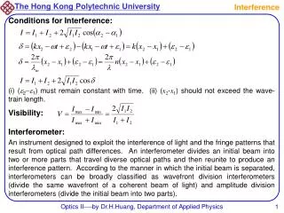
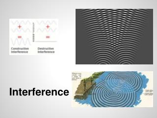
Interference coupling mechanisms source victim coupling path Direct coupling Near field coupling Radiated coupling
coupling path 1. Direct coupling Coupling via power or signal lines Common impedance coupling
1. Direct coupling Coupling via power or signal lines
1. Direct coupling Common impedance coupling
coupling path 2. Near field coupling Magnetic or inductive coupling Electric or capacitive coupling
2. Near field coupling Magnetic or inductive coupling
2. Near field coupling Electric or capacitive coupling
2. Near field coupling • Spacing
coupling path 3. Radiated coupling Field generation Wave impedance
coupling path 4. Coupling modes Differential mode Common mode Antenna mode
Coupling modes Differential mode
Coupling modes Common mode
Coupling modes Antenna mode
Interference coupling mechanisms Emissions Radiated emission Conducted emission
Emissions Radiated emission • Radiation from the PCB
Emissions Radiated emission • Radiation from cables
Interference coupling mechanisms Immunity
Causes of internal radar interference Standards used : MIL-HDBK-237
What is jamming [2] • jamming is a form of Electronic Warfare where jammers radiate interfering signals toward an enemy's radar, blocking the receiver with highly concentrated energy signals
jammers can be categorized into two general types: 1- barrage jammers 2- deceptive jammers (repeaters). • Barrage jammers attempt to increase the noise level across the entire radar operating bandwidth. • Barrage jammers are often called maskers • Barragejammers can be deployed in the main beam or in the side lobes of the radar antenna
Repeater jammers carry receiving devices on board in order to analyze the radar’s transmission, and then send back false target-like signals in order to confuse the radar • There are two common types of repeater jammers: 1- spot noise repeaters 2- deceptive repeaters
Self-Screening Jammers (SSJ) • The single pulse power received by the radar from a target of RCS , at range , is • The power received by the radar from an SSJ jammer at the same range is • BJ > Br jammer bandwidth is usually larger than the operating bandwidth of the radar.
S/J ratio for a SSJ • The jamming power is generally greater than the target signal power. • The ratio s/j is less than unity.
As the target becomes closer to the radar, there will be a certain range such that the ratio s/j is equal to unity. • This range is known as the cross-over range. • The range window where the ratio S ⁄j is sufficiently larger than unity is denoted as the detection range. • In order to compute the crossover range
For a radar with a detection range of 100 km for an RCS of 5m2, [3]
This program calculates the cross-over range and generates plots of relative S and J versus range normalized to the cross-over range
Wave length in dB Conversion to db
Stand-Off Jammers (SOJ) • ECM signals from long ranges. • The power received by the radar from an SOJ jammer at range RJ is • The gain term G’ represents the radar antenna gain in the direction of the jammer
The inputs to the program ‘soj_req.m’ are the same as in the SSJ case , with jammer peak power Pj = 5000w , jammer antenna gain Gj =30 dB, radar antenna gain on the jammer G’ =10dB, and radar to jammer range R= 22.2 Km
EMC design • There are many design considerations that need to be taken • Cable wiring • Connectors • Grounding • Shielding • The reference for good consideration is standard
Cable coupling analyses • The result
Reference • [1] H.-D. Brüns, H. Singer, “Computation of Interference in Cables Close to Metal Surfaces,” IEEE Int. Symposium on EMC, Denver, 1998, pp 981-986 • [2] CRC Press - MATLAB Simulations for Radar Systems Design • [3] Air and Space borne Radar Systems - An Introduction • [4] Intro duction to airborne radar second edition George W. stimson • [5] Tim Williams, EMC for Product Designers, Fourth edition • [6] CLAYTON R. PAUL, Introduction to Electromagnetic Compatibility, Second Edition • [7] Frank H. Sanders Effects of RF Interference on Radar Receivers • [8] EMI from Cavity Modes of Shielding Enclosures – FDTD Modelling and Measurements,” M. Li, J. Nuebel et al, IEEE Trans on EMC, Vol. 42, No. 1, February 2000, pp. 29-38.