Download
1 / 9
90 likes | 272 Vues
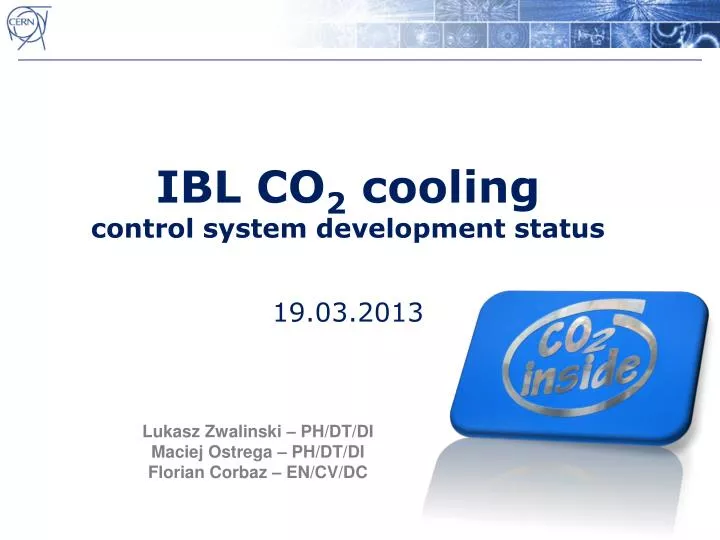
IBL CO 2 cooling control system development status 19.03.2013. Lukasz Zwalinski – PH/DT /DI Maciej Ostrega – PH/DT/DI Florian Corbaz – EN/CV/DC. IBL CO2 cooling control system development . Presentation overview: Hardware A) control cabinets B) accumulator local box

E N D
IBL CO2 coolingcontrol system development status19.03.2013 Lukasz Zwalinski – PH/DT/DI Maciej Ostrega – PH/DT/DI Florian Corbaz – EN/CV/DC
IBL CO2 cooling control system development • Presentation overview: • Hardware • A) control cabinets • B) accumulator local box • System architecture • Electrical connections • Cabling • Control system development status: • Fixed control rack position • Prepared first version of control documents: • - ATLAS IBL CO2 Cooling Station Functional Analysis For Continuous Process Control (CPC) EDMS 1233462 • - Specification of control interface between cooling control system and ATLAS Detector Control System EDMS 1233464
Control cabinets • Status: • Control/electrical rack layout design completed • Electrical schematics nearly completed by Florian • 95% of control hardware components ordered and delivered • Assembly by EN/CV already started IBL A IBL B Layout prepared by S.Berry Lukasz Zwalinski IBL 18th March 2013
Intermediate control box for maintenance operation • What does it serves for? • local maintenance manipulation independent from control racks! • Status: • Rack layout design completed • Electrical schematics completed by Maciej • Assembly in PH/DT started • Still minor components to be ordered • Front panel to be graved with P&ID by NIKHEF • Characteristics • Individual 24V DC hot swappable power supplies • Separate 230V power • Local valve position indicators (LED + signal send to both PLCs) • Local valve manipulation panel • Local vacuum pressure indicator • Local vacuum pump start/stop with protection • Emergency switch Lukasz Zwalinski IBL 18th March 2013
System architecture Detector Control System OWS OWS OWS DIP EN/CV Terminal server Critical data tunnel from PLC to DCS CERN GPN Central Control Room CERN Technical Network Local MODBUS TCP/IP Local MODBUS TCP/IP IBL plant A IBL plant B Premium CPU Premium CPU Local Touch Screen Local Touch Screen WAGO I/Os WAGO I/Os Hardware signals FESTO FESTO Pneumatic lines Pneumatic lines ATLAS DSS Lukasz Zwalinski IBL 18th March 2013
System architecture System architecture conclusions: PVSS server location agreed with ATLAS ID and DCS to be in CCC Server is already installed in CCC The data base for long data storage has to be selected! (ATLAS vs LHC TIMBER) PLC will send ~20 most critical signals with direct MODBUS protocol to the DCS Rest of the signals will be send to DCS using the DIP protocol The UNICOS library extended for WAGO Ethernet IP modules There will be common accesses from Detector Cooling CCM IBL A IBL B Lukasz Zwalinski IBL 18th March 2013
Electricity, system powering – ATLAS UPS • Status: • Architecture, power requirements and electrical hardware discussed with Wieslaw Iwanski & EN/EL James Devine • EN/EL with an agreement of the EN/CV will provide us ASAP Information about the staring point • Florian will make TRACIEL calculations to verify protection sizing and guarantee correct selectivity • Wieslaw agreed to supply all IBL control system from UPS • UPS feeder will be decided depending on whether or not IBL system shall be – and if so in which part – interlocked with DSS ??? Lukasz Zwalinski IBL 18th March 2013
Cabling • Status: • Cable schedule with patching details completed (cable size, pinouts, wire colours • NIKHEF is informed and terminals are send to them with patching details • Signal cables installation between USA15 and UX15 already started by S. Malyukov • Power cable for dummy load still need to be pulled once the TRACIEL calculations are completed • Thermocouple type K halogen free cable for dummy load protection has to be purchased and pulled • DSS and Bake-out cables has to be pulled whenever we know the destination racks • Input file to print out ATLAS DB cable labels ready for Irina Malyukova • The communication with Bake-out system has to be defined (we send 24V or Bake-out system sends 24V?) Junction Box in UX15 USA15 Level 3 Control B Maintenance Box Control A Cooling Plant A Chiller A Accumulator A&B Cooling Plant B Chiller B Lukasz Zwalinski IBL 18th March 2013
Thank You Lukasz Zwalinski IBL 18th March 2013