Download
1 / 24
280 likes | 566 Vues
Carbon Nanotube Polymer Composite Saturable Absorbers in Photonic Bandgap Fibers . Jennifer Black 2010 Kansas State University Advisor: Dr. Brian Washburn. Overview. Goal: Create a unique saturable absorber to mode-lock a fiber laser

E N D
Carbon Nanotube Polymer Composite Saturable Absorbers in Photonic Bandgap Fibers Jennifer Black 2010 Kansas State University Advisor: Dr. Brian Washburn
Overview • Goal: Create a unique saturable absorber to mode-lock a fiber laser • How: Inserting a carbon nanotube polymer solution into the center hole of a photonic bandgap fiber • Why: To mode-lock a laser with high repetition rate and increase intercavity energy
Mode-Locked Lasers • Laser that produces a series of ultrashort pulses (infinite pulse train) • Two techniques: • Active: uses optical modulator • Passive: may use a saturable absorber
Mode-locking Pictures from Rick Trebino lecture notes
Passively Mode-Locked Lasers Use of a saturable absorber (SA) in the cavity creates the pulse train. SA are materials with non-linear optical properties that attenuate low optical intensities. SA Gain [1] Fourier Transform! Mirror Output Coupler
Frequency Combs • The carrier envelop offset and can be set and the comb stabilized • Applications of stable combs: • Metrology • Optical clock • Telecommunications • Doppler lidar • Spectroscopy [2] The frequency comb (red) can be beat against an unknown frequency (blue). If the comb frequencies are known, then the unknown frequency can be determined. fn = nfr + foffset
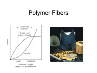
Passively Mode-Locked Fiber lasers • Optical fibers can be used as waveguidesfor lasers that are: • Cheap • Portable • Robust • “Easy” • Carbon Nanotube Fiber Lasers: • High rep rate vs. HNLF • Low Power Threshold! VS. HNLF Damaged Nanotubes!
Core Cladding n1 = 1.5 n2 = 1.52 Core Cladding Standard optical fiber: total internal reflection Photonic bandgap fibers n1 = 1.5 n2 = 1.0 Hollow capillary fiber: 4% loss per bounce. • Bragg scattering forbids radial propagation --or-- • Photonic crystal forbids propagation everywhere except at defect. ~1.1 1.0 PBG fiber
Photonic Bandgap Optical Fibers (PBG) • Using 10 µm inner diameter PBG fiber • Want CNT/PMMA solution in center hole • Have PBG guide like solid core fiber d = 10 mm
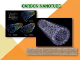
Carbon Nanotubes (CNT) Transmission vs. Wavelength Curves for CNT of Different Mean Diameter • Diameter of CNT change transmission wavelength dependence • How to incorporate CNT into fiber laser? [3] [4] Mean diameter = 1.35 nm Mean diameter = 1.2 nm
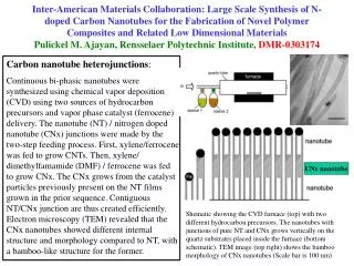
CNT/Polymer Solution • Polymer (we use PMMA) used to disperse CNT homogenously – nPMMA = 1.49 • Put inside of PBG fiber and guide like solid core fiber • Step 1: 3mg CNT and 10mL of a solvent are sonicated for 3 hours • Step 2: 37mg of PMMA are added and sonicated for an additional 2.5 hours • Solvents used: • - Acetone • - Anisole A few days later Carbon Nanotube precipitant
Method • Taper PBG fiber: • Cleave fiber where photonic crystal has collapsed and center hole is all that is left open:
Method • Apply vacuum to cleaved end of PBG while cleaved end is in CNT/PMMA solution CNT/PMMA solution FIBER Microscope Vacuum chamber Vacuum Chamber CNT/PMMA solution
Testing the Fibers • Test small piece of sample in a pre-existing fiber laser Laser Diode LD Butt-couple SA (..?) into laser cavity Output Coupler Gain
Testing the Fibers Cleaved fiber from the laser Fiber Laser PBG sample Sample is butt-coupled on both sides to a pre-existing fiber laser
Optical Spectra • Mode-locked • Broad spectra • Continuous Wave (CW) • Sharp peak
Results for Acetone • Acetone Sample: • Lasing CW but not mode-locking… • Not stable • Poor solvent for this process • Laser possibly boiling away solvent – optical limiting • … Try a different solvent! Pout = 0.5 mW; length = 4 cm
Results for Anisole • Anisole Sample: • Also lasing CW • Not mode-locking Pout = 120 µW Length = 3.0 cm Pout = 0.8 mW Length = 2.8 cm
Conclusion • Believe solution is in fiber: • Possible Problems: • Not enough CNT per sample length • What next…? • CNT fluoresce • Change composition CNT/PMMA solution “Clean PBG” PBG with solution
Acknowledgments • Jinkang Lim, Shun Wu, Andrew Jones, Rajesh Thapa, May Ebbeni, Chenchen Wang • Dr. Washburn, Dr. Corwin, Dr. Weaver • Mike Wells and Scott Chainey • NSF; ASOFR
References • [1]: http://www.optik.uni-erlangen.de/mpf/php/abteilung2/index.php?show=research&in=precisionmeasurements&and=rim • [2]: http://www.rp-photonics.com/frequency_combs.html • [3]: http://www.justmeans.com/Carbon-Nanotube-based-Batteries-for-HEVs/11428.html • [4]: Sze Y. Set, H. Yaguchi, Y. Tanaka, M. Jablonski. Ultrafast Fiber Pulsed Lasers Incorporating Carbon Nanotubes. IEE Journal of Selected Topics in Quantum Mech., Vol. 10, No. 1
CNT Deposition • Process: • 10mW at 1560 nm through SMF and put into solution for 30s • Out of solution for 1 min • Throughput checked • Continue until loss = -3dB • Put into fiber laser cavity and mode-locks EDFA LD • CNT/ethanol solution: • 0.5mg CNT • 20mg Ethanol Nanotubes about fiber taper
Single Walled Carbon Nanotubes Single wall carbon nanotubes have semiconductor, semimetal or metallic properties depending on the chiral vector of the nanotube Excitonic absorption in the semiconductor nanotube is responsible for the saturable absorption property Ultrafast recovery of the saturable absorber is due to metallic nanotubes serving a recombination centers