Download
1 / 21
210 likes | 391 Vues
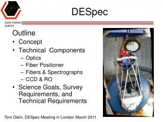
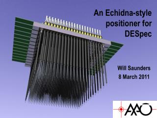
An Echidna-style positioner for DESpec. Will Saunders AAO 27 th June 2011. General considerations. DESpec requires ~4000 fibres over 450mm focal plane: N fibres = 1832 (10/p) 2 7mm pitch (or less!) WFC delivers F/2.88 – F/2.96 - perfect for standard fibres

E N D
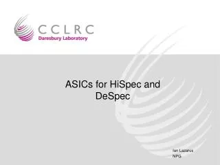
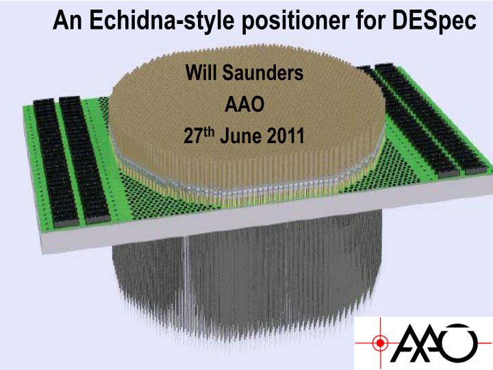
An Echidna-style positioner for DESpec Will Saunders AAO 27th June 2011
General considerations • DESpec requires ~4000 fibres over 450mm focal plane: Nfibres = 1832 (10/p)2 7mm pitch (or less!) • WFC delivers F/2.88 – F/2.96 - perfect for standard fibres • Plate scale 17.6"/mm + 1.8" apertures ~100m core fibres. • Fibre systems want telecentric input curved focal plane • Wide Field Corrector > 1 metre diameter - lots of room • Cost, simplicity, modularity, paramount.
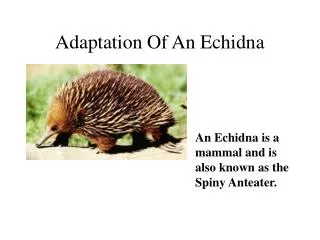
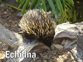
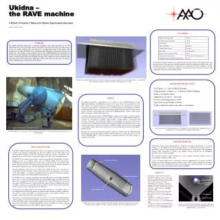
FMOS instrument for Subaru needed 400 fibres in 150mm diameter focal plane - so needed a completely new and very compact design. • Echidna uses 'spines’ – fibres in carbon-fibre spines, with a piezo-driven magnetic stick-slip mechanism to position fibres. • 7.2mm pitch between fibres • Few m positioning accuracy • Very short repositioning times*
Echidna features • 400 fibres, 7.2mm pitch. • Few seconds per repositioning iteration, spines reposition in parallel*, several iterations per fibre. • <10 m final positioning error. • Spines introduce inevitable focal errors, (up to 86 m for Echidna). • Spines also introduce telecentricity errors, up to 2.75 for Echidna. • Patrol radius allows 3-fold covering of focal plane. When Ntargets Nfibres, fibering efficiency is ~85%, versus 63% for LAMOST-style positioner. NOT TO SCALE
WFMOS-Echidna proposal 2005 proposal for 4500 fibre positioner for Gemini, primarily to study dark energy. Very close to DESpec requirements!
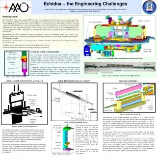
WFMOS concept design • Proposal evolved into concept design for Subaru. • 500mm FOV, 3000 spines, 8.7mm pitch, adjustable length. • Curved focal plane (5m ROC). • Fully prototyped at AAO • Lost out to COBRA!
WFMOS-A concept design • 2008 proposal for WFMOS for AAT • 1600 spines over 450mm FOV, 11.2mm pitch • Simplified design, 7 spine parts 3, no glue • Pitch limited to ~8.5mm by 8mm ball bearing • Smaller pitch requires ¼" ball-bearing, would give <7mm pitch. Should be fine but must prototype!
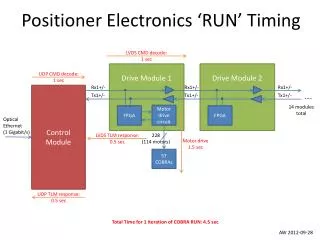
Metrology and positioning times • Must back-illuminate spines. Either back-illuminate science fibres, or add extra metrology fibres to spines. • Image from single 4Kx4K camera mounted in Cass chimney, 1/20 pixel centroiding (easy) gives 6m precision. • Individual moves < 10s, but need few iterations to reach 10m precision ("Par 3"). 130s conservative overall budget.
Rest of Package: AAO provides whole data taking package, based on our 2dF, 6dF, AAOmega, Echidna, Ozpos, HERMES experience. Now routine to modify package for different instruments and telescopes. Package includes: • Observing planning software • Configuring software • Interface between instrument and telescope (instrument usually drives telescope) • Data reduction pipeline
Configuring software Configuring software includes guide stars, target priorities, checking for validity over range of Hour Angles, etc. Now based on simulated annealing, can't do better!
Configuring software Configuring software includes guide stars, target priorities, checking for validity over range of Hour Angles, etc. Now based on simulated annealing, can't do better!
Patrol radius vs yield Yield (fraction of fibres used) and completeness (fraction of targets observed) both increase with patrol radius. Product peaks at 70%, when Ntargets ~ Nfibres 7mm pitch, 4-7mm patrol radius (1.5 field)
Data reduction • AAO has state-of-the-art fibre spectroscopy data reduction pipeline. Very flexible and robust. • PCA (Principal Component Analysis) sky subtraction now routine Poisson-limited sky subtraction with dedicated sky-fibres.
Data reduction • AAO has state-of-the-art fibre spectroscopy data reduction pipeline. Very flexible and robust. • PCA (Principal Component Analysis) sky subtraction now routine Poisson-limited sky subtraction with dedicated sky-fibres.
Proposed DESpec design • R&D program to determine minimum viable spine pitch, aim for 6.75mm (4000 fibres total). • Use Polymicro FBP fibre – cheap, available, excellent FRD and transparency (few % over 30m for 600-1000nm). • Use 104/125m core/cladding: fits standard telco connectors, cladding thickness ok to 1m (10), gives 1.83" aperture on sky. • Make modules curved (only 3.2mm sag) and tapered, to fit together to form section of sphere. All modules identical, all spines same length, all telecentric. • Maximum defocus 57m, (1/3"), ~2% light loss. • Maximum telecentricity error 2, vs 10 beam radius, ~2 % light loss.
Spectrograph thoughts: Plan A • 6000Å -10000Å coverage @ 3Å resolution (R=3300@10000Å) 1333 spectral resolution elements. • Can cover with single 4K detector if PSF FWHM 3 pixels. • 100m fibres, 3 pixel FWHM camera speed F/1.4 Schmidt optics • VPH gratings have high efficiency only over small field angles, so want long camera large beam-size (250mm minimum). • Large beam also means small obstruction losses for Schmidt cameras, so attractive option. Obstruction losses partially shadowed by prime focus obstruction anyhow. • Schmidt correctors cheaper now with MRF technology. • Smart to design for 2 x 2K x 4K detectors in each camera, would need ~6 spectrographs only.
Spectrograph thoughts: Plan A Schmidt/Schmidt design, 250mm beam, F/1.3 camera. F/2.75 collimator 2 correctors needed. Fixed format, so can put prisms between VPH and correctors, to reduce air-glass surfaces. Almost all cheap glass. Optics are good (rms radius < 10m). Cost of optics $80K ROM Dewar is whole camera or CCD + field flattener?
Spectrograph thoughts: Plan B • 2-armed design removes many constraints. • 5000Å -10000Å coverage @ 2.5Å resolution (R=4000@10000Å) 2000 spectral resolution elements. • Can cover with 2 x 4K detector if PSF FWHM 4 pixels. • 100m fibres, 4 pixel FWHM camera speed F/1.85 transmissive design is fine (and more efficient). • VPH angles still want long camera and large beam-size. • Smart to design for 2 x 2K x 4K detectors in each camera, would need ~8 spectrographs.
Spectrograph thoughts: Plan B • JHU WFMOS (evolution of SDSS to 4K x 4K detectors) is very efficient, compact, and affordable @ $1M each. • 159mm beam, f/1.5 cameras. Would need to add collimator correctors for DESpec • Smart to design for 2 x 2K x 4K detectors in each camera, would need ~8 spectrographs.