Download
1 / 31
330 likes | 844 Vues
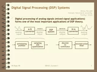
Signal Processing for OFDM Communication Systems. Eric Jacobsen Minister of Algorithms, Intel Labs Communication Technology Laboratory/ Radio Communications Laboratory July 29, 2004. With a lot of material from Rich Nicholls, CTL/RCL and Kurt Sundstrom, of unknown whereabouts. Outline.

E N D
Signal Processing for OFDM Communication Systems Eric Jacobsen Minister of Algorithms, Intel Labs Communication Technology Laboratory/ Radio Communications Laboratory July 29, 2004 With a lot of material from Rich Nicholls, CTL/RCL and Kurt Sundstrom, of unknown whereabouts
Outline • OFDM – What and Why • Subcarrier Orthogonality and Spectral Effects • Time Domain Comparison • Equalization • Signal Flow • PAPR management • Cool Tricks
Digital Modulation Schemes • Single Carrier • PSK, QAM, PAM, MSK, etc. • Demodulate with matched filter, PLLs • Common Standards: DVB-S, Intelsat, GSM, Ethernet, DOCSIS • Multi-Carrier • OFDM, DMT • Demodulate with FFT, DSP • Common Standards: DVB-T, 802.11a, DAB, DSL-DMT
What is OFDM? • Orthogonal Frequency Division Multiplexing • Split a high symbol rate data stream into N lower rate streams • Transmit the N low rate data streams using N subcarriers • Frequency Division Multiplexing (FDM) & Multi-Carrier Modulation (MCM) • N subcarriers must be mutually orthogonal Subcarrier spacing = f Partition available bandwidth into N orthogonal subchannels Stream -N/2 Complex Baseband OFDM Signal s(t) . . . High Rate Complex Symbol Stream Stream 1 Serial to Parallel Hold (Thold = 1/f sec) f . . . 0 -N(f)/2 (N-1)(f)/2 . . . Stream N/2-1 OFDM Conceptual Block Diagram
Why OFDM? • Reduces symbol rate by more than N, the number of subcarriers • Fading per subcarrier is flat, so single coefficient equalization • Reduces equalizer complexity – O(N) instead of O(N2) • Fully Captures Multipath Energy • For Large Channel Coherence Time, OFDM/DMT can Approach “Water Pouring” Channel Capacity • Narrowband interference will corrupt small number of subcarriers • Effect mitigated by coding/interleaving across subcarriers • Increases Diversity Opportunity • Frequency Diversity • Increases Adaptation Opportunities, Flexibility • Adaptive Bit Loading • OFDMA • PAPR largely independent of modulation order • Helpful for systems with adaptive modulation
Downsides of OFDM • Complexity • FFT for modulation, demodulation • Must be compared to complexity of equalizer • Synchronization • Overhead • Cyclic Extension • Increases the length of the symbol for no increase in capacity • Pilot Tones • Simplify equalization and tracking for no increase in capacity • PAPR • Depending on the configuration, the PAPR can be ~3dB-6dB worse than a single-carrier system • Phase noise sensitivity • The subcarriers are N-times narrower than a comparable single-carrier system • Doppler Spread sensitivity • Synchronization and EQ tracking can be problematic in high doppler environments
Subcarrier Orthogonality • Orthogonality simplifies recovery of the N data streams • Orthogonal subcarriers = No inter-carrier-interference (ICI) • Time Domain Orthogonality: • Every subcarrier has an integer number of cycles within TOFDM • Satisfies precise mathematical definition of orthogonality for complex exponential (and sinusoidal) functions over the interval [0, TOFDM ] • Frequency Domain Orthogonality: ICI = 0 at f = nf0 f f Some FDM systems achieve orthogonality through zero spectral overlap BW inefficient! OFDM systems have overlapped spectra with each subcarrier spectrum having a Nyquist “zero ISI pulse shape” (really zero ICI in this case). BW efficient!
Practical Signal Spectra Single carrier signals require filtering for spectral containment. This signal has narrow rolloff regions which requires long filters. OFDM spectra have naturally steep sides, especially with large N. The PAPR is often higher, which may result in more spectral regrowth. The blue trace is an unfiltered OFDM signal with 216 subcarriers. The red trace includes the effects of a non-linear Power Amplifier.
Time-Domain Comparisons By greatly increasing the symbol period the fading per subcarrier becomes flat, so that it can be equalized with a single coefficient per subcarrier. The addition of the cyclic prefix eliminates Inter- Symbol Interference (ISI) due to multipath.
Frequency Domain Equalization • Design System Such That TDelay Spread < TGuard and BCoherence > BSubcarrier • Subcarriers are perfectly orthogonal (no ISI or ICI) • Each Subcarrier experiences an AWGN channel • Equalizer Complexity : Serial Data Rate = 1/T, OFDM Symbol Rate = 1/(NT) • FEQ performs N complex multiplies in time NT (or 1 complex mult per time T) • Time domain EQ must perform MT complex multiplies in time T where M is the number of equalizer coefficients Channel Frequency Response (at time t) Subcarrier n Frequency
802.11a Processing • 802.11a is a TDD contention-based, bursty protocol • Full acquisition, synchronization, and EQ training can be performed for each burst or “frame” • The “short training symbols” provide timing, AGC, diversity selection, and initial carrier offset • The “long training symbols” provide fine synchronization and channel estimation • Two FFT periods allow 3dB increase in channel estimation SNR by combining (averaging) the estimates • Tracking is facilitated by the four pilot tones
802.11a Time/Frequency Signal Structure DATA FRAME Short Training Symbols Long Training Symbols Data Symbols 8.125 MHz … FREQUENCY 53 Subcarriers (48 data, 4 pilot, 0 @ DC) 0 … -8.125 MHz Indicates Pilot Tone Location 800 ns 4 s TIME
DVB-T Time/Frequency Signal Structure Since DVB-T is a continuous transmit signal, channel estimation is facilitated easily by rotating pilots across the subcarrier indices. Interpolation provides channel estimation for every subcarrier. This figure is from reference [4]
Peak to Average Power Ratio • Single Carrier Systems • PAPR affected by modulation scheme, order, and filtering • Constant-envelope schemes have inherently low PAPR • For example: MSK, OQPSK • PAPR increases with modulation order • e.g., 64-QAM PAPR is higher than QPSK • As Raised Cosine excess bandwidth decreases, PAPR increases • Squeezing the occupied spectrum increases PAPR • Multi-Carrier Systems • PAPR affected by subcarrier quantity and filtering • PAPR is only very weakly connected to modulation order • PAPR increases with the number of subcarriers • Rate of increase slows after ~64 subcarriers • The Central Limit Theorem is still your friend • Whitening is very effective at reducing PAPR • Symbol shaping decreases PAPR
64-QAM 20% RRC 64-QAM OFDM-48 802.11a 64-QAM OFDM-240 P(PAPR < Abscissa) PAPR (dB) PAPR with 240 subcarriers N = 240 requires no more than 1dB additional backoff compared to 802.11a, and about 3.5dB more than a single-carrier system. The results shown use only data whitening for PAPR reduction. Additional improvements may be possible with other techniques.
PAPR Mitigation in OFDM • Scrambling (whitening) decreases the probability of subcarrier alignment • Subcarriers with common phase increase PAPR • Symbol weighting reduces the effects of phase discontinuities at the symbol boundaries • Raised Cosine Pulse weighting • Works well, requires buffering • Signal filtering • Easier to implement
Time-Domain Weighting The phase discontinuities between symbols increase the size of the spectral sidelobes. Weighting the symbol transitions smooths them out and reduces the sidelobe amplitudes. Typically Raised- Cosine weighting Is applied. Tapered Regions This figure is informative content from the IEEE 802.11a specification. The two-fft period case applies only to preambles for synchronization and channel estimation.
Effect of Symbol Weighting With no RC weighting With 1% RC weighting Applying a tiny bit of symbol weighting in the time domain has a significant effect on PAPR. In this case only 1% of the symbol time is used for tapering. The blue trace is prior to the PA, the red trace after. Application of the 1% RC window meets the green transmit mask.
Cool and Interesting Tricks • OFDMA • Different users on different subcarriers • Adaptive Bit Loading • Seeking water filling capacity • Adaptation to Channel Fading • Adaptation to Interference
OFDMA Subcarrier Division The 802.16 standard describes multiple means to implement OFDMA. In one mode each user’s signal occupies contiguous subcarriers which can be independently modulated. Another mode permutes each user’s subcarriers across the band in a spreading scheme so that all user’s subcarriers are interlaced with other user’s subcarriers. The first method allows for adaptive modulation and the second method increases frequency diversity.
Subcarrier Division with TDM Each color is for a distinct terminal.
Channel Frequency Response Multipath Frequency Selective Fading v = 100 km/hr f = 2 GHzt = 0.5 m sec Shannon’s Law applies in each “flat” subinterval
High SNR At Receiver Low SNR At Receiver Sub Carriers OFDM “Symbol” Adaptive Bit Loading Frequency (MHz) -5 -4 -3 -2 -1 0 1 2 3 4 5 5 0 6 bps/Hz -5 4 bps/Hz -10 Response (dB) 2 bps/Hz -15 Deep Fade (Bad) -20 0 bps/Hz -25 -30 Channel Bandwidth 64 QAM 16 QAM QPSK
References [1] IEEE Std 802.11a-1999 [2] Robert Heath, UT at A, http://www.ece.utexas.edu/~bevans/courses/realtime/lectures/20_OFDM/346,22,OFDM and MIMO Systems [3] Hutter, et al, http://www.lis.ei.tum.de/research/lm/papers/vtc99b.pdf [4] Zabalegui, et al, http://www.scit.wlv.ac.uk/~in8189/CSNDSP2002/Papers/G1/G1.2.PDF
Backup No! – Go forward!
Cyclic extension removes ISI and ICI ! Cyclic Prefix (Guard Interval) • Delay Spread Causes Inter-Symbol-Interference (ISI) and Inter-Carrier-Interference (ICI) • Non-linear phase implies different subcarriers experience different delay (virtually all real channels are non-linear phase) • Adding a guard interval between OFDM symbols mitigates this problem • Zero valued guard interval will eliminate ISI but causes ICI • Better to use cyclic extension of the symbol Symbol #1 Symbol #2 TOFDM TOFDM TG TFFT Subcarrier #2 ICI Subcarrier #1 (delayed relative to #2 ) Guard interval eliminates ISI from symbol #1 to symbol #2 3.5 cycles of subcarrier #1 inside the FFT integration period ICI !
DVB-T Time/Frequency Signal Structure Since DVB-T is a continuous transmit signal, channel estimation is facilitated easily by rotating pilots across the subcarrier indices. Interpolation provides channel estimation for every subcarrier. This figure is from reference [3]
SCM Sensitivity (margin) Complexity Memory Phase noise sensitivity Frequency registration Reduced PA Backoff Less Overhead (no cyclic prefix) OFDM Single Frequency Networks Simple EQ Flexibility Statistical Mux OFDMA – BW, TDMA LOW SNR, avoid DFE PAPR not affected by modulation order. Automatically integrates multipath. IEEE Politics Advantages