Download
1 / 13
130 likes | 209 Vues
ok. stop. not ok. ok. stop. ok. stop. not ok. ok. stop. Evolution of the gas system control for flight. WINCAN Macro. WINCAN. WINCAN Diagnostic. WINCAN Basic. WINCAN Monitor. Code and Manual available at: http://www.cern.ch/spada/AMS/. TRD Status display.

E N D
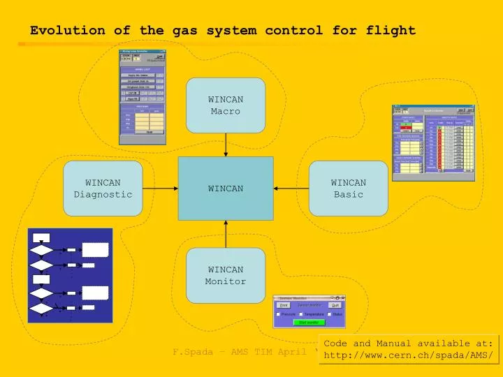
ok stop not ok ok stop ok stop not ok ok stop Evolution of the gas system control for flight WINCAN Macro WINCAN WINCAN Diagnostic WINCAN Basic WINCAN Monitor Code and Manual available at: http://www.cern.ch/spada/AMS/ F.Spada – AMS TIM April ‘06
TRD Status display ISS <-> ground data communication – software location WINCAN Macro state definitions JMDC HRDL WINCAN Monitor check list ISS GROUND WINCAN Macro State definitions, mixing) log files PC WINCAN Diagnostic WINCAN Basic user interfaces WINCAN Monitor display F.Spada – AMS TIM April ‘06
Security checks • Security conditions to be verified before operating on the system • On valves: • Forbidden to open a valve if the last temperature readout is too old or if temperature is under a fixed threshold • Forbidden to open a valve if a heater is on (not enough power) • Before opening a valve on the tank - D vessel line, disable the upstream one (avoid two valves open at a time) • On heaters • No heater on if a Marotta valve is open (not enough power) • Keep average dissipation (duty cycle) under a fixed threshold • These conditions are automatically taken into account in what follows F.Spada – AMS TIM April ‘06
box S • Disable all Marotta • Heaters off box C • Disable all Marotta • Close V8 • Pumps off • HV off • Heaters off Defined states of the gas system/1 • To minimize the communication with space: • define states of the system – the definition resides on the JMDC • from ground only send command “bring system in status x” • Examples of defined states: state “Ground” manifold • Close all VA, VB, VC, VD F.Spada – AMS TIM April ‘06
box C box S box C box C box S box S • bring to “Ground” state • open V18 • bring to “Ground” state • bring to “Ground” state • bring to “Ground” state • open V4 Defined states of the gas system/2 state “Empty” verify temperature ok not ok heaters on verify pressure in D not ok ok F.Spada – AMS TIM April ‘06 stop
box S • bring to “Ground” state box C • bring to “Ground” state manifold • bring to “Ground” state box C • open V8 manifold • open all VA, VB, VC, VD Defined states of the gas system/3 state “Ready” verify temperature ok not ok heaters on F.Spada – AMS TIM April ‘06
box S • bring to “Ready” state box C • bring to “Ready” state manifold • bring to “Ready” state box C • pumps on box C • HV on Defined states of the gas system/4 state “Run” verify P2 ok not ok stop verify temperature ok not ok F.Spada – AMS TIM April ‘06 heaters on
Diagnostic procedures/1 Example of a procedure to determine the status of electromechanical components: check of the Marotta valves in the box S after a dysfunctional behaviour of the pressure in the D vessel. F.Spada – AMS TIM April ‘06
Diagnostic procedures/2 open V1A open V2A open V3A V1A = ok V1B = ? V10A = ? V10B = ? V2A = ok V2B = ? V3A = ok V3B = ? V20A = ? V20B = ? measure P2A ok stop not ok measure P2B ok P2A = ko stop not ok open V10A open V2A open V3A V1A = ko V1B = ? V10A = ok V10B = ? V2A = ok V2B = ? V3A = ok V3B = ? V20A = ? V20B = ? measure P2 ok stop not ok F.Spada – AMS TIM April ‘06
Diagnostic procedures/3 open V20A open V20B open V2B open V3B V1A or V10A = ok V1B = ? V2A or V3A = ko V10B = ? V2B = ok V3B = ok V20A = ok V20B = ok measure P2 ok stop not ok open V1B open V2B open V3B (V1A & V10A) or V20A or V20B = ko V1B = ok V10B = ? V2A = ? V2B = ok V3A = ? V3B = ok measure P2 ok stop not ok F.Spada – AMS TIM April ‘06
Diagnostic procedures/4 open V10B open V2B open V3B (V1A & V10A) or V20A or V20B = ko V1B = ko V10B = ok V2A = ? V2B = ok V3A = ? V3B = ok measure P2 ok stop not ok open V20A open V20B open V2A open V3A V1A & V10A = ko V20A & V20B = ok V1B or V10B = ok V2A = ok V2B or V3B = ko V3A = ok measure P2 ok stop not ok stop P2a, P2b ko??? F.Spada – AMS TIM April ‘06
Summary • WINCAN split in four branches • Basic • Monitor • Macro • Diagnostic • Security conditions included • Defined states of the system To do: • Continue with safety study • More diagnostic procedures • … F.Spada – AMS TIM April ‘06
State “Ground” Box S Manifold disable V1a disable V10a disable V2a disable V3a disable V20a disable V4a disable V1b disable V10b disable V2b disable V3b disable V20b disable V4b close VimA close VimB close VimC close VimD i = 1, …,5 (6) m = 1, …,8 heaters off Box C disable V6a disable V18a disable V6b disable V18b close V8a close V8b heaters off CP1 off CP2 off F.Spada – AMS TIM April ‘06 HV off