Download
1 / 25
250 likes | 386 Vues
Auto-Chromatic Instrument Tuner. Erin Smith Advisor: Dr. James Irwin Date: November 20th, 2000. Presentation Overview. Project Summary Milestones & Critical Problems Future Work. Project Summary. Brief Overview of Operation State of Received Tuner Proposed Modifications.

E N D
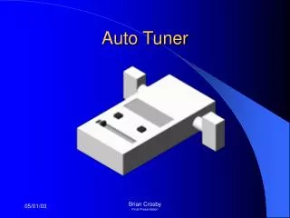
Auto-Chromatic Instrument Tuner Erin Smith Advisor: Dr. James Irwin Date: November 20th, 2000
Presentation Overview • Project Summary • Milestones & Critical Problems • Future Work
Project Summary • Brief Overview of Operation • State of Received Tuner • Proposed Modifications
Overview of Operation • The auto-chromatic tuner is a self contained tool that is used to determine the pitch and intonation of a musical instrument in real time
Functional Description • Inputs • Microphone • Pitch selector • Power/Mode Switch • Outputs • Pitch indicator • Digital tuning indicator • Speaker • 8031 Microcontroller
Auto-Chromatic Tuner LED Display Pitch Up Octave Up E b 6 Pitch Down Octave Down R Y G Y R Auto Manual Tuning Tuning Off Audible Pitch Pitches: G: Green LED ± 5 cents Y: Yellow LED ± 5-15 cents R: Red LED ± 15-50 cents
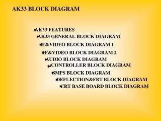
Audio In Threshold Detector Timer/ Counter Microphone Amplifier Automatic Gain Control Clock Divide By 2 Tree Switched DC Power to all sub- systems - Parts which do not work, or have not been included yet Bus Overflow Power/ Mode Switch Mode Bus Microprocessor Display Control Bus Analog Meter DC Power Bus Bus Bus Tuning LED’s Function Generator Pitch Selector Frequency Look-Up Table Pitch Indicator Pitch Indicator Speaker Driver Selected Pitch Out Speaker
Audio In Threshold Detector Timer/ Counter Microphone Amplifier Automatic Gain Control Clock Divide By 2 Tree Switched DC Power to all sub- systems - Parts which were modified Bus Overflow Power/ Mode Switch Mode Bus Microprocessor Display Control Bus Analog Meter DC Power Bus Bus Bus Tuning LED’s Function Generator Pitch Selector Frequency Look-Up Table Pitch Indicator Pitch Indicator Speaker Driver Selected Pitch Out Speaker
Start Initialization Mode Read Mode/ Power Switch Audible Reference Pitch Auto Tune Display Pitch Manual Tune Setup and Start Counter Adjust Frequency Driver Counter Overflow Yes No Read Counter Tuning Mode Display Results
State of Received Tuner • Auto-tune worked with pre-selected octave only • Manual tune supposedly worked, or had some portion working • Analog and Digital Tuning worked • Display worked correctly • Pieces of software worked, but not all in one program
State of Received Tuner • Tuner did not work as expected when connected to power supply • Programmer was faulty, PAL’s were broken • Unit did not work until mid-March • Analog meter ceased to work (not sure if problem with hardware or software) • No software located for manual tune
Proposed Modifications • Manual Tune completion • Automatic Gain Control • Expand Digital Tuning • Auto-Tune Mode completion
Manual Tune • Software for Manual Tune could not be located • Scope was too large, given that no code was available to work from • Due to time constraints, was not able to complete Manual Tune mode
Automatic Gain Control • Attempted several different configurations in the Spring • Gain circuit with Varistor • Circuit with an FET
Varistor Vin Vout LPF Gain circuit with Varitstor in parallel Low amplitude signal Vin Vout gnd Gain circuit with FET in feedback loop
Automatic Gain Control • Found article with an AGC circuit which involves a digital potentiometer • Parts did not come in, so AGC could not be implemented
x(t) y(t) E(t) CONTROL + _ Eref AGC Circuit which utilizes a Digital Potentiometer
Digital Tuning • Wanted to expand digital tuning from 5 LED’s to 9 LED’s • Intended to take place of analog meter • Expanded the truth/logic tables • Not enough memory or bits available to implement the expansion • Required major re-design of hardware and doing the wire wrapping over again
Excerpts of Expansion of the Truth Tables (formerly only A15-A11 needed)
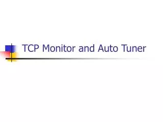
Auto-Chromatic Tuner LED/LCD Display E b 6 Pitch: Octave: R O Y B G B Y O R Auto Manual Tuning Tuning Off Audible Pitch Pitches: G: Green LED ± 3 cents B: Blue LED ± 4-10 cents Y: Yellow LED ± 11-20 cents O: Orange LED ± 21-30 cents R: Red LED ± 31-50 cents
Auto-Tune Mode • Worked with pre-selected octave only • Learned how Timer 0 Overflow worked in relationship to counting the period • When overflow occurred, decremented the octave and reset the divide by 2^n • Once a pitch is successfully detected, reset the divide by 2^n to the 9th octave • Device is then ready to search again
Milestones & CriticalProblems • Critical Problems • Unit did not work initially • Not enough memory to expand LED’s • Lack of software for manual tune • Parts for AGC did not come in
Milestones & CriticalProblems • Milestones • Getting unit up and running • Expanding tables for LED’s • Determined a good duty cycle and waveform for the Audible Reference Pitch with a function generator • Determined design for AGC circuit • Successfully implementing Auto Tune Mode
Future Work • Manual Tune • Audible Reference Pitch • Expanded LED Display • Packaging • Automatic Gain Control • New Hardware:microphone, speaker, CPU, and memory