Download
1 / 27
320 likes | 630 Vues
A Modular Approach. Software Defined Radio. What is SDR?. Software Defined Radio

E N D
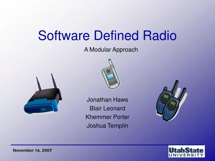
A Modular Approach Software Defined Radio
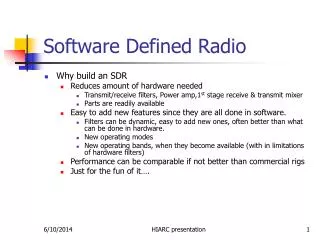
What is SDR? Software Defined Radio “A radio communication system which can potentially tune to any frequency band and receive any modulation across a large frequency spectrum by means of as few as hardware possible and processing the signals through software” (Wikipedia, “Software Defined Radio”) One device serves multiple purposes Significant utility in military and cellular markets Precursor to “Cognitive Radio” Radio will alter transmission and reception parameters (modulation, frequency, and power) to avoid interference and improve overall QoS
History Many wireless devices are designed to serve a single purpose Cell phone, wireless router, GPS receiver, AM/FM radio, etc. Many current software radio groups exists GNURadio, HPSDR, SDR Forum, and others
Problem Design a software defined radio that has the ability to: Change modulation techniques “on-the-fly” Avoid unwanted white noise Provide a means to easily implement the same software on other radios
Solution Code and implement on a DSP various algorithms that provide the desired functionality of the radio Keep code modular (C++ classes)
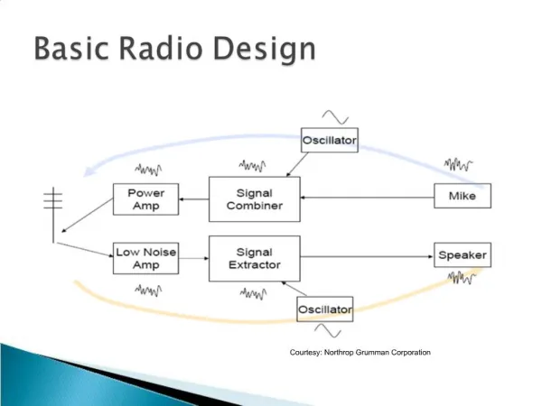
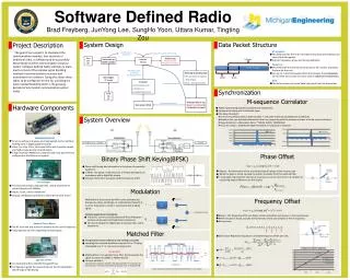
Transmitter Coder Block Add bits to data stream to provide error protection (data redundancy) Bit/Symbol Convert the data stream into transmission symbols for transmission Transmit Filter Shape the symbols to the desired waveform Modulator Modulate the signal for transmission
Channel Channel properties Model a wireless channel with an appropriate transfer function White Noise WSS random process modeled as a process with a constant power spectral density Interference Other interference modeled as normal random variables
Receiver LNA/AGC Amplify signal to receiver circuit levels Sampler Sample the received signal for digital processing Demodulator Demodulate the received signal Carrier Recovery Recover the phase of the carrier signal Matched Filter Filter designed to match the transmitting filter Timing Recovery Recover original clock of the transmitter Equalizer Distortion compensation Decoder Decode symbols into appropriate bit stream
Software AlgorithmDevelopment Process Algorithms will be Developed in MATLAB Tested in SIMULINK Converted to C/C++ Tested in C/C++ model Compared to SIMULINK Verified on DSP board
Implementation Decisions C++ Ease of transition between MatLab and C++ C++ will provide modular classes and functions Inheritance and Virtual Functions DSP Boards can be programmed with C/C++ Linux Documentation Cross-Platform Macintosh and IBM Compatible
Modularity Utilities Class AM Modulation Class QA Modulation Class FM Modulation Class Transceiver Transmitter Receiver
Modulation Techniques Software Defined Radios allow for multiple modulation techniques NO additional hardware is needed Filtering can also be accomplished without any additional hardware.
Amplitude Modulation (AM) V(t) = Vocos(2ft + ) For AM the value Vo is varied to change the amplitude of the signal.
Frequency Modulation (FM) • V(t) = Vocos(2ft + ) • For FM f is varied.
Quadrature AM V(t) = Vocos(2ft + ) + Vosin(2ft + ) For QAM, two signals that are out of phase by 90 degrees are used simultaneously.
Digital Modulation The techniques that were discussed are for analog modulation. The process is similar for digital modulation The digital modulation types are: ASK, FSK, and QASK Once these techniques are realized, they can be adapted to achieve other modulation types BPSK, QPSK, …
Matched Filters • Maximize the SNR to improve QoS • Receiver filter is matched to the transmitter filter by the relationship
Carrier and Timing Recovery Data aided vs. Non-data aided • Data Aided • Only applicable when data symbols are detected reliably • Requires phase and frequency information of the carrier • Based on decisions made by receiver • Non-Data Aided • Independent of data symbols • Can be used for both tracking and acquisition • Not as accurate as Data-aided while tracking
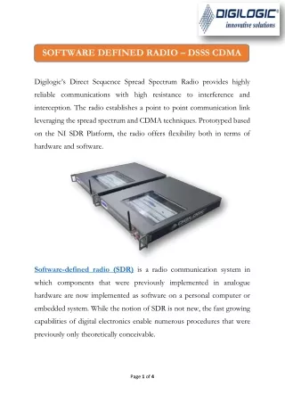
Spectrum Digital DSP Boards SDI TMS320C6713 DSP Boards • 225 MHz • 512KB Flash • 8MB SDRAM • Microphone, Speaker, Mono In/Out audio ports • USB Interface
Preliminary Testing MATLAB simulation using AM modulation Receiver rectifies signal and detects peaks Raw Signal Demodulated Signal
Thank you! We appreciate your time and thank you for coming!