Download

1 / 94
940 likes | 946 Vues
Presentation on Transmission Rings in Jaipur SSA. Network Elements of Jaipur SSA. Exchanges + RSUs + DLCs(Urban) 3 + 58 + 12 Exchanges Rural 143 TAX (L1 ) 03 GSM GMSC 01 GMSC/MSS 05

E N D
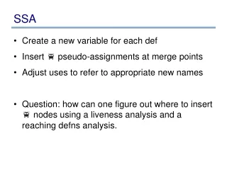
Network Elements of Jaipur SSA • Exchanges + RSUs + DLCs(Urban) 3 + 58 + 12 • Exchanges Rural 143 • TAX (L1 ) 03 • GSM GMSC 01 • GMSC/MSS 05 • RNC 01 • GSM BSC 10 • GSM BTS(2G) 520 • GSM BTS(3G) 282 • HUB 14 • SUB HUB 53
Network Elements of Jaipur SSA • CDMA MSC 02 • CDMA BTS 92 (41 U + 51 R) Broadband Network • Tier I 3 p3 & 1 p2 • Tier II 12 p3 & 07 p2 • OCLAN Switch 14 • DSLAMs 254 • Internet Lease Lines 75
Network Elements of Jaipur SSA • FTTH Equipments 61 OLTs • Buildings 207 MPLS Network • DXC 03 • Vmux 99
Requirement • Optical fiber cable (High Count) • Optical Access network (OAN) • Optical Rings for making Network Most reliable.
Solutions • 96 F /48 F Cable • 400 Kms of cable in 7 polygons with manholes at every 200 M. • STM-16 Rings planned in Urban & Rural areas. • STM-1 ADMs , STM-1 CPEs are deployed to provide connectivity in the same rings. • 1 Gigabit Ethernet link are planned from each SDCC to the LDCC. • Apart from this the same station may have connectivity to Two or more SDCCs on the same ring at one STM-1 TM level each.
Solutions • i.e a minimum of 8 STM-1 MUX may need to be planned at each SDCC. • The number of ADM-16 nodes in the ring may be planned as 6 Nos. at the most . • This shall enable at least 2 STM-1 dropping at each en route stations. • All ADMs to have GE and FE interfaces. • The SDCAs HQ have been planned with 32 Chl. 2.5 G DWDM systems and STM-16 rings will be connected to DWDMs for inter SDCA connectivity.
Future Network Vision - 2009 40 Chl – 10G/Tera bit DWDM Backbone Proposed L1 ASON enabled High end OXC Proposed 32 Chl – 2.5 G DWDM Backbone Proposed L2 L3 32 Chl – 2.5 G/12Chl 10G DWDM Backbone Proposed Multi ADM On LH links Proposed 2048 X 2048 High end OXC Proposed + MADMs MADMs & MSPP STM-16 City Access rings or SDCAs Rings STM-64 Endlinks for GSM MSCs NIB Routers / BB Lan Switches/ COTs/ BSCs/ TAXs/ STM-1 and CPE City Access Rings GSM BTS /DLCs /DSLAMs/RSUs/Customers National network plan
MADM MADM DWDM MADM MADM MADM MADM MADM MADM ADM ADM MADM MADM ADM ADM ADM ADM ADM Proposed Connectivity
NIB Gateway Video server National/SSA DWDM Network City DWDM OADM Network MSPP Ring Network STM-16 STM-64 Rings STM-16/4/1 Rings COT ring COT ring Router STM-16/4/1 Rings RTs Media Gateway COT ring RSUs/ RLUs/Leased lines RSUs/ RLUs/Leased lines GSM MSCs COT ring LE/ Tandem/ TAX COT ring Access / Service Network Planning
DSLAM DSLAM DSLAM 12F 12F 12F 6F DSLAM 6F 12F TIER-II SWITCH 24F 6F DSLAM DSLAM DSLAM Requirement of BB connectivity
JAIPUR GSM, WLL, NIB SAMBHARMain Exchg MOZMABAD Exchange/ Dslam/BTS/ PMux JHAG Exchange/ Dslam/ BTS SAWARDA Exchange/ Dslam/ BTS BORAJ Exchange/ Dslam/ WLL BTS/ Boraj, Ugariawas BTS MAHALA Exchange/Dslam/BTS/ Leased Line Connectivity Diagram of Rural Ring DUDU RSU/ OC LAN RURAL RING – JPR-16
BAJAJ NAGAR RNC VAISHALI NAGAR 3G Hub/ Leased Ckt/(Bhankrota, Bindayka, Dhankya, Vaishali, Tagore Ngr, Chitrkoot, Hirapura, Begus, Mundia Ramsar, Officer campus, Anupam vihar) GSM/WLL BTS, Prithvi raj Ngr RSUs JHOTWARA 3G Hub/BTS/ WLL BTS/ (Arya Ngr, Devdhara Col, Shankar Vihar, Shri footwear) GSM BTS VDN-II 3G Hub/RSU/ BTS/leased ckt/ VDN II GSM/WLL BTS VKIA 3G Subhub/ RSU/ Leased Ckt/ BTS/ VKI WLL/ GSM BTS Connectivity Diagram of Urban Ring MI ROAD MI Rd 3G Hub, Bindayka 3G Hub/ leased Ckt URBAN RING
Power Supply • The power required by us is negligible compared to the other industrial users. Telecom had power problems since the time remembered. Only we have this problem other users do not have them.
Power Supply • There is a very fundamental difference in the way we use it. This creates different and difficult problems for us. We convert it to 50 V DC by the phase controlled rectifiers .
Power Supply • We know that in a single phase load the current in the neutral is the same as the phase . In a three phase load the current in the neutral will always be less than any of the phase current.
Power Supply In two phase load also, the neutral current can never exceed the phase currents. But in a phase controlled three phase rectifier the neutral current depends on the phase switching instants .
Power Supply • In AC/DC conversion, even if the average load per phase is equal, the instantaneous load is never balanced. It creates high neutral currents which is generally not thought by us.
Power Supply • In worst case the average neutral current can average three times to the phase currents. the power network is not designed for this extreme condition.
Power Supply • This high neutral current and the high impedance of the neutral path is a major reason for voltage swings, higher harmonics and faults on the feeder cables. Please consider next diagrams.
Power Supply • Ip IL 1 : 1 Load • There can be no primary current if there is no secondary current ideally.
IL Load I IC I = (3-4)% of IL Equivalent Ckt • Only negligible magnetizing current (3-4% of rated load) can flow in primary.
Power Supply If the neutral is open on any side then imbalance current more than the magnetizing current can not be delivered in a three phase system. Still three phase balanced load can be delivered. See next fig.
5 A say Load I1 L1 I2 I3 L2 L3 Rated current per phase = 100A say More than 5% imbalance load cannot be supplied, if primary side neutral is open
Power Supply If the neutral resistance is more (greater than 0.5 ohm) then the voltage shall start dipping on imbalanced loads. No stabilizer can correct the situation . See next fig.
Power Supply imbalance load puts a stringent requirement for Earth resistance Rated current per = say100A 63 KVA TH Rated voltage =say 220V 5 A say j L o I 1 L1 ¥¥¥¥ a ¥¥¥¥ d I 2 I 3 L2 ¥¥¥¥ ¥¥¥¥ L3 ¥¥¥¥ ¥¥¥¥ RE Open Open , voltage drop = 100V If RE = 1 1 W , voltage drop = 10V If RE = 0.1 W Rated load resistance = 220/100 = 2.2 W s
Power Supply • We have taken the RMS value of load for above calculations. In an AC/DC converter the phase current is a peaking pulse of 1-2 milli seconds.
Its magnitude is 15-20 times of the time average. The resulting dip in phase voltage at the switching instant is 15-20 times more than calculated above. Power Supply
The resulting instant dip in the phase voltages can not be felt in a normal way as every thing will appear and measure normal to the operator. Power Supply
The module will not be able to deliver the rated output current and voltage. The out puts will fluctuate and the module will be declared faulty. Power Supply
So, the small impedance and the continuity of the neutral is very important. Generally the neutral is taken from the improperly grounded earth path. Power Supply
Power Supply • Metallic connection of the neutrals are not given importance. The area of the neutral is half of the phase conductor in a power cable. The SMPS and this neutral are not matching .
Either we have to change the grounding practices of the neutral which does not appear feasible, or we must change the SMPS design which is easier and possible. Power Supply
Power Supply Now we discuss the second part of the power problem. We are using single phase or three phase SMPS. The three phase SMPS’s are in fact three single phase SMPS working on diffrent phases.
Power Supply • Conventional power plants had a Delta connected transformer at the input. It was independent of the neutral and was protected against over voltages by the B-H curve of its iron core.
Power Supply B-H Curve V input V input In conventional power plant input impulse voltage does not go in the output.
Power Supply • The SMPS does not have these natural protections. So, We are using i.e. lightening arrestors , surge suppressors and contactors for over voltage protection .
a b c N Surge suppressors Lightening Arrestors Lightening arrestor & Surge Suppressor
Power Supply • The lightening arrestors operate if the input voltage is Mega Volts for a short time , The surge protectors operate if it is in KV. The contactors disconnect at more than 500V
Power Supply Three phase SMPS are actually three single phase SMPS connected in star. Their out put is in parallel. The SMPS has an input rectifier and capacitor filter.
Power Supply So it can be modeled like a capacitor when the thyristor is triggered on. During switching on the mains it takes surge current. It appears as shown
Power Supply • We see that the terminal voltage across every SMPS is nearly 240 volt if the neutral is connected to the star point. But if it is not or it has high impedance then….