Download
1 / 35
350 likes | 664 Vues
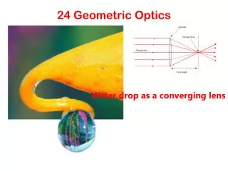
Geometric Optics. Flat Mirrors Spherical Mirrors Images Formed by Refraction Thin Lenses Optical Instruments Cameras Projectors Vision Telescopes Microscopes. Images - Terminology. p : Object Distance. q : Image Distance.

E N D
Geometric Optics • Flat Mirrors • Spherical Mirrors • Images Formed by Refraction • Thin Lenses • Optical Instruments • Cameras • Projectors • Vision • Telescopes • Microscopes
Images - Terminology p: Object Distance q: Image Distance Real Images: When light rays pass through and diverge from the image point. Virtual Images: When light rays do not pass through but appear to diverge from the image point. Magnification
Images Formed by Flat Mirrors The image is virtual For flat mirrors, M = 1 • The image distance is equal to the object distance. • The image is unmagnified, virtual and upright. • The image has front-back reversal.
Concept Question An observer O, facing a mirror, observes a light source S. Where does O perceive the mirror image of S to be located? • 1 • 2 • 3 • 4 • Some other location. • The image of S cannot be seen by O when O and S are located as shown.
Some Examples Multiple Images Formed by Two Mirrors Rearview Mirror
Concave Spherical Mirrors Spherical Concave Mirror A real image is formed by a concave mirror Paraxial Approximation: Only consider rays making a small angle with the principal axis Spherical Aberration
Image Formation Focal Point
Convex Spherical Mirrors The image formed is upright and virtual
Sign Conventions for Mirrors • p is positive if object is in front of mirror (real object). • p is negative if object is in back of mirror (virtual object). • q is positive if image is in front of mirror (real image). • q is negative if image is in back of mirror (virtual image). • Both f and R are positive if center of curvature is in front of mirror (concave mirror). • Both f and R are negative if center of curvature is in back of mirror (convex mirror). • If M is positive, image is upright. • If M is negative, image is inverted.
Ray Diagrams For Mirrors • Ray 1 is drawn from the top of the object parallel to the principal axis and is reflected through the focal point F. • Ray 2 is drawn from the top of the object through the focal point and is reflected parallel to the principal axis. • Ray 3 is drawn from the top of the object through the center of curvature C and is reflected back on itself.
Image From a Mirror f = +10 cm Concave Mirror (b) p = 10 cm (c) p = 5 cm (a) p = 25 cm
Sign Conventions for Refracting Surfaces • p is positive if object is in front of surface (real object). • p is negative if object is in back of surface (virtual object). • q is positive if image is in back of surface (real image). • q is negative if image is in front of surface (virtual image). • R is positive if center of curvature is in back of convex surface. • R is negative if center of curvature is in front of concave surface.
Flat Refracting Surface The image is on the same side of the surface as the object.
Apparent Depth The image is virtual
Thin Lenses The image formed by the first surface acts as the object for the second surface where, q1< 0 Lens Makers’ Equation
Concept Question A parallel beam of light is sent through an aquarium. If a convex glass lens is held in the water, it focuses the beam • closer to the lens than • at the same position as • farther from the lens than outside the water.
Lens Types Converging Lenses f1: object focal point f2: image focal point Diverging Lenses
Sign Conventions for Thin Lenses • p is positive if object is in front of lens (real object). • p is negative if object is in back of lens (virtual object). • q is positive if image is in back of lens (real image). • q is negative if image is in front of lens (virtual image). • R1 and R2 are positive if center of curvature is in back of lens. • R1 and R2 are negative if center of curvature is in front of lens. • f is positive if the lens is converging. • f is negative if the lens is diverging.
Ray Diagrams for a Converging Lens • Ray 1 is drawn parallel to the principal axis. After being refracted, this ray passes through the focal point on the back side of the lens. • Ray 2 is drawn through the center of the lens and continues in a straight line. • Ray 3 is drawn through the focal point on the front side of the lens (or as if coming from the focal point if p < f) and emerges from the lens parallel to the principal axis.
The image is real and inverted The image is virtual and upright
Ray Diagrams for a Diverging Lens • Ray 1 is drawn parallel to the principal axis. After being refracted, this ray emerges such that it appears to have passed through the focal point on the front side of the lens. • Ray 2 is drawn through the center of the lens and continues in a straight line. • Ray 3 is drawn toward the focal point on the back side of the lens and emerges from the lens parallel to the principal axis.
Examples A diverging lens with f = -20 cm h = 2 cm, p = 30 cm A converging lens with f = 10 cm (a) p = 30 cm The image is real and inverted (b) p = 10 cm The image is at infinity (c) p = 5 cm The image is virtual and upright The image is virtual and upright
Java Applet for Lens and Mirrors • http://www.phy.ntnu.edu.tw/java/index.html
I1 O I2 f2 f1 Combination of Thin Lenses • First find the image created by the first lens as if the second lens is not present. • Then draw the ray diagram for the second lens with the image from the first lens as the object. • The second image formed is the final image of the system.
15 cm 20 cm 10 cm I1 I2 O f1 = 10 cm f2 = 20 cm Example
Object and Image Distances Converging Lens Diverging Lens
The Simple Magnifier Use a lens near the eye to make an object seem larger (occupy a larger angle at the eye).
Compound Microscope Use a lens combination to make small objects near the objective seem more visible.
Refracting Telescope Use a lens combination to make distant objects more visible