Download

1 / 32
330 likes | 426 Vues
Chap 11 SWITCHING CIRCUITS. BY: PRIYANK SHAH PARIN SHAH. INTRODUCTION.

E N D
Chap 11SWITCHING CIRCUITS BY: PRIYANK SHAH PARIN SHAH
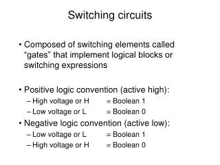
INTRODUCTION • A Constituent Electric Circuit which receives, stores or manipulates information in coded form to accomplish the specified objective of the system is known as the Switching Circuit. • Switching Circuits performance can be presented as truth tables. They are two valued attributes where condition attribute represent input variable and decision attribute represent output variables.
MINIMIZATION OF PARTIAL DEFINED SWITCHING FUNCTIONS • Applying rough set philosophy to switching function minimization, • Considering this input a,b,c,d and e from the switching circuit as condition attributes an d output f as the decision attribute. ab c f d e
MINIMIZATION OF TABLE • Combination of input variables not present in the table will never occur. • Table is consistent as combination of all input variable values are different, hence the corresponding switching functions is well defined. • Removing the variable a from the previous table we get the following table.
ANALYSIS OF TABLE • Variable c is superfluous in the definition of the switching . • Now combining the identical rules we get the following compact form of the table removing the column c.
We can observe from the table that the decision rules b1d0e0 f1 a1e0 f1 b1e1 f0 are reduced. Whereas remaining core values d0 not form reducts.
MINIMAL SET OF DECISION RULES • Decision rules covering minimal set of all condition for each decision class are:: • | b1d0e0 | = {2,3,4,7} | a1e0 | = {4,5,6,7,9} • But Decision class “1” does not cover set {1,8}. • From table we find the missing rules are : |a0d1e1|={1} |b0d1e1|={1,8} |a0b0e1|={1} |a1b0d1|={8,9}
MINIMAL SOLUTION • Thus the 3 minimal solution are : • b1d0e0 V a1e0 V a0d1e1 f1 • b1d0e0 V a1e0 V b0d1e1 V a1b0d1 f1 • B1d0e0 V a1e0 V a0b0e1 V a1b0d1 f1
The solution can be written in more convenient form • bd’e’ V ae’ V a’def Where x and x’ denotes variables without and with negation respectively. The corresponding switching circuits can be easily implemented using “and” , “or” and “not” gates.
MULTIPLE-OUTPUT SWITCHING FUNCTION • Synthesis of the multiple output switching function by treating the this kind of functions as single set of output functions and applying the procedures used previously. • Considering this input - a , b , c and d from the switching circuit as condition attributes and output - e and f as the decision attribute. a b e c f d
REPLACE DECISION ATTRIBUTE BY SINGLE FOUR VALUED VARIABLE Y.
GROUP AND REMUNERATE ROWS OF THE TABLE W.R.T. OUTPUT VARIABLE
COMPUTE Y REDUCTS OF INPUT VARIABLE: REMOVING I/P VARIABLE a
COMPUTE Y REDUCTS OF INPUT VARIABLE: REMOVING I/P VARIABLE b
COMPUTE Y REDUCTS OF INPUT VARIABLE: REMOVING I/P VARIABLE c
COMPUTE Y REDUCTS OF INPUT VARIABLE: REMOVING I/P VARIABLE d
EQUIVALENT DECISION ALGORITHM • The equivalent decision algorithm from the above minimal solutions are as follows :: 1.) a0b0d0 i 2.) aob1d1 i 3.) a1c1 ii 4.) a0b1d0 iii 5.) a1b0d0 iii 6.) b0c0d1 iv OR a0b0d0 V aob1d1 i a1c1 ii a0b1d0 V a1b0d0 iii bocod1 iv
DECISION ALGORITHM IN BOOLEAN NOTATION • Representing the algorithm in boolean notation we get the following. Also by representing in this form it gives user with easy implementatio of the switching circuits using AND, OR and NOT gates. • a'b'd‘ i a'bd i ac ii a'bd' iii ab'd' iii b'c'd iv OR a'b’d’ V a’bd i ac ii a'bd’ V ab’d’ iii b'c’d iv