Download
1 / 1
10 likes | 102 Vues
FPCL Positioning Speed. c. c. 1. 2. 3. 4. 5. Matrix. Application definition. Design Entry Schematics, Verilog VHDL (Netlist). Functional Simulation Verify correct logic functionality Estimated timing or no timing. Meged Ofer Cellot inc.

E N D
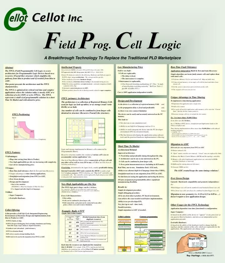
FPCL Positioning Speed c c 1 2 3 4 5 Matrix Application definition • Design Entry • Schematics, Verilog VHDL (Netlist) • Functional Simulation • Verify correct logic functionality • Estimated timing or no timing Meged Ofer Cellot inc. Mobile: +972-58 - 829942 Office: +972-9 - 8842554 e-mail: Meged@cellot.com www.Cellot.com ellot ellot Algorithm Test& Debug • TimingSimulation • Post placement timing info FPCL • Design Implementation • Design Installation Synthesis • (Bitstream) • Design rule checking • Logic partitioning/ fitting • Block placement • Routing , (Logic Cell Array) • Create programming file • Static timing analysis • Post placement timing info • Faster result than timing simulation ASIC ASIC 1000 FPGA • In system Debugging • For re Programmable parts Topology Controller Controllers Processors FPCL mapping FPGA programming Design Verification Complexity MCM Cellot’s solution Common programming Application definition Algorithm Test& Debug CellotInc. Field Prog. Cell Logic A Breakthrough Technology To Replace the Traditional PLD Marketplace Run-Time Fault Tolerance Application independent Built In Test and Auto Recovery: Simple algorithm can locate faulty atomic cells and replace them with intact cells: • Perform a Memory Test for each unused cell. Map out faulty ones. • Using external memory, set an empty cell with the functional data of any chosen cell. • Set the correct connections and switch between the cells. • The original cell is now free for test. Abstract The FPCL (Field Programmable Cell Logic) is a new architecture for Programmable Logic Devices based on a recursive (Fractal like) structure which simplifies the pathway from Idea to product and (if needed) from Idea to ASIC. This poster presents the architecture and the FPCL characteristics. The FPCL is optimized for critical real time and complex applications where the solution today is mostly ASIC or a collection of a few DSPs or a few FPGAs. The FPCL represents a small sized programmable solution in a short Time To Market and with attractive price. Intellectual Property Patent filed in the USPTO in November 1999 and PCT filing in November 2000. PCT approved in July 2002. Europe grant: July 2003. PCT p.n.: WO01/39249. Patents 49 claims are related to the following Hardware and Software aspects: • FPCL chips’ unique architecture. The concept and the specific, • New methods of electronic hardware design, • New methods of electronic devices testing in the manufacturing process, • Built In testing capabilities and auto-recovery - automatic mapping of faulty segments in the chip, • Automatic conversion process to ASIC, • Future products based on the technology mainly related to super computers. Low Manufacturing Price Yield is very high: • Cells are replaceable, • The delay is fixed, • The interconnect is complete. • Interconnect is replaceable, • Clos Network Switching methodology (C. Clos, “A study of non-blocking switching networks,” Bell Syst. Tech. J., pp.406–424,Mar.1953.) Core is 100% application independent testable. Unique Advantage in Time Sharing To implement a timesharing application: • Implement the application (for a single slot), • Add a slot counter, • For each cell used for application, add a memory cell to store the “Current State” that the slot the counter points to, • Increase storage cells size to include the slot counter. FPCL (primary) Architecture The architecture is a collection of Registered Memory Cells used for logic (as look up tables) or as storage (read / write RAMs) or as both. Any number of cells can be combined to form larger cells identical in structure (Recursive Fractal Like structure). Design and Development As the device is a collection of registered memory Cells and, As the propagation delay is fixed and predictable and, As there is no cross connect limitation hence: The device can be easily and accurately mirrored on the PC memory. This leads to: • Very fast one to one simulation tool, • Ability to use high level language such as C++, • Ability to easily integrate the device into the PC developer environment (PCI Acceleration board), • The line between developing the application using software tools and the practical hardware implementation is blurring. Ex: 1 to (more than) 50,000 Filters If one filter uses 21.5 K Bytes, In a 2.5M Bytes FPCL device, straight forward duplication leads to 116 Filters at highest rate. Time sharing implementation allows more than 50,000 filters with reduced working frequency. ( 2.5M/43K = 58 Each can implement 1000 filters in 1/2000 of the speed. Can be doubled each time the timesharing counter increased by one bit. Can be set to be any number e.g. 3, 4, 5, …, 32, …, 137, …, 59000) Migration to ASIC EDA tools for easy migration from FPCL to ASIC • Remove unused cells, • “Open” matrix switches are removed, “closed” ones are replaced by links, • Remove the Matrix Control Memory (MCM) and the topology controller, • Memory cells which implements applications are converted to ROMs (auxiliary hardware is removed), • RAM used for storing data are left intact, • Generate VHDL net-list. The ASIC created keeps the same timings relations! Short Time To Market Architectural Related: Improved architecture: • Fixed delay and predictable timing throughout the chip, • Architecture can be one to one mirrored on the PC, • Cells can be combined to form larger cells, • Every point measurement access (including in ICE mode). Real Time, one-to-one, Simulation Tools / ICE tools, Ability to use abstract high-level language (better then VHDL), Straightforward one-to-one migration from FPCL to ASIC, No link between testing the application and testing the device, I/O pins assignment programmability allows significant manufacturing flexibility. Logic and storage implemented in Memory cells connected by Programmable Matrix. Recursive structure enables the creation of various cell’s sizes to accommodate various applications’ size. One level Non-Blocked Matrix allows connectivity of Every cell with any other cell as well as every I/O to any cell (Base on Clos Network Switching methodology.) Fixed delay, determined by the input clocks, enablespredictable timing, Internal Controller (8051 style) controls the MCM to enable a high level of failures immunity: FPCL technology can “Map itself” and define and avoid faulty cells. The controller can be replaced by high end processor (DSP) to integrate both implementation styles. FPCL Features • Advantages: • Huge time saving from Idea to Product, • Very high applicability per die size increasing with complexity, • Low device manufacturing price. • Unique: • Run-Time fault tolerance (Built In Test and Auto Recovery), • Unique advantages in time-sharing applications, • Straightforwardmigration from FPCL to ASIC, • Ever Green design, • Design and Development: • One to One simulator (WYSIWYG = What You Simulate Is What You Get) • C++ Support and other high level languages. • Other: • Super Computers • Evolvable Hardware. Ever Green Design Upwards / Backwards compatibility and geometry independence: As: • Each bigger size cell can be seamlessly used instead of lower size cell, • Few lower size cells can always be combined to form bigger size cell, Migration to new geometry (i.e. 0.18 to 0.13 to 0.09 to …) doesn’t require a new application design. Very High Applicability per Die Size The FPCL logic part is huge: can be 2.5M Bytes For comparison: 100,000 cells of 4 inputs and 1 output (each can be implemented by 16 bits memory block) are equivalent to only 200K Bytes (100,000 x16 bits = 200KBytes). Every Cell Characteristics: • Write ability, • Cells can be combined to form larger cells, • Full connectivity: each point can be connected to any other point, so there is no such resource limitation. Results in: Simple development procedure, Simple debugging procedure, All in one from idea to product, PC based environment, Can achieve the exact needed result before implementation, Ability to use pre-developed IPs, Very fast (up to real – time) tools, Parallel activities, Simple migration to ASIC (if needed). Other Usages for the FPCL Technology Application dependent (run time) functional re-configuration: Super Computer: Is based on the ability of the device to “appear” to any processor as one passive block of memory, and also as an independent active application provider. Evolvable Hardware: Is based on the ability of the hardware itself to change both the topology and the contents of the cells, which are responsible for the application: The application can change itself. • Cellot Offering • Cellot provides a Full Life Cycle Integrated Engineering Environment of Electronic Design and implementation from Idea to Product or ASIC: • FPCL Family of chips, • FPCL Design & Debugging Tools including Simulation and Testing Tools like Scope, Logic Analyzer, Signal Generators, • Synthesis tools (download – fault tolerance), • PCI Acceleration Board, • IPs to be re-used as design building blocks, • EDA tools to be used in the migration from FPCL to ASIC. Example: Radix 4 FFTLength: 1024, 16 Bits Complex Each time the resources are duplicated the transform time is divided. For example: If the FFT is implemented utilizing 900K Bytes the transform time will be 2.0 or 1.25 micro seconds for Standard cells or Full Custom implementations. While at MAPLD 2003 Contact: Roy Hastingsat (818) 414-3577.