Download
1 / 12
120 likes | 216 Vues
Why 20 MHz Channelization in HTSG?. John Terry, Ph.D NRC Dallas. 20 MHz Channels & the PAR and 5 Criteria. Broad Market Potential In order to obtain the broadest market, the HT standard must be a global standard

E N D
Why 20 MHz Channelization in HTSG? John Terry, Ph.D NRC Dallas John Terry Nokia
20 MHz Channels & the PAR and 5 Criteria • Broad Market Potential • In order to obtain the broadest market, the HT standard must be a global standard • Hence, channel bonding is not suitable for global standardization since it does not meet the European regulatory specification of 20 MHz channelization • Economic Feasibility • Technically, channel bonding is feasible; however, it does not increase aggregatenetwork capacity by itself • Thus, can MIMO technology and channel bonding both be developed cost effectively? • Most of the available cost data for RF chains are based on 20 MHz channelization designs • Distinct Identity • HTTG will result in a wireless LAN with higher throughput than provided by 802.11a, 802.11b and 802.11g. • Neither channel bonding nor UWB meets this criterion on a per Hz basis. John Terry Nokia
Aggregate Network Capacity Study John Terry Nokia
Transmitter Antenna Height LOS n1 n2 OBS n Fresnel distance Low (3.7m) 2.18 3.29 2.58 Reference path loss (1 meter) Medium (8.5m) 2.17 3.36 2.56 High (13.3m) 2.07 4.16 2.69 Path Loss ModelsWideband PCS Model from Feuerstein • Line of Sight (LOS) • Obstructed Line of Sight (OBS) Feuerstein, M.J., Blackard, K.L., Rappaport, T.S., Seidel, S.Y., and Xia, H.H., “Path Loss, Delay Spread and Outage Models as Functions of Antenna Height for Microcellular System Design,” IEEE Transactions on Vehicular Technology, Vol. 43, No 3, pp. 487- 498 August 1994. John Terry Nokia
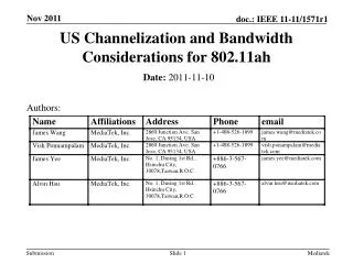
2 2 7 3 7 3 1 1 6 4 6 4 5 2 5 2 7 3 2 7 3 1 3 1 7 4 6 1 4 6 5 4 5 6 2 2 5 7 3 7 3 1 1 6 4 4 6 5 5 Simulator Approach – Seven Frequencies • Center cell is the reference • Center cell is randomly populated • with 1 – 20 users • Each of the six adjacent cells with • the same frequency is also • populated with 1 – 20 users • Interference is calculated for • the six strongest interferers to • the center of the reference cell John Terry Nokia
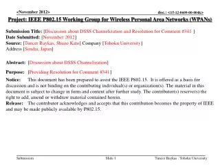
1 2 1 3 1 4 2 4 1 2 3 3 1 4 2 1 3 4 2 4 2 1 3 3 1 4 2 4 3 2 1 3 Simulator Approach – Four Frequencies • Center cell is the reference • Center cell is randomly populated • with 1 – 20 users • Each of the six adjacent cells with • the same frequency is also • populated with 1 – 20 users • Interference is calculated for • the eight strongest interferers to • the center of the reference cell • Note that four interferers • dominate John Terry Nokia
Capacity Study Assumptions • Link closes at 1% PER • Channel bonding PER performance has 3 dB penalty compared to the corresponding 802.11a performance due to the doubling of the noise bandwidth for the same tx power. • Capacity for both channel bonding and non-bonding cases are computed using reuse factors (Fr) of 4 and 7. • Bonding case will require reuse factor of 4 while non-bonding case, 7. • The base rate set for channel bonding without any antenna enhancements includes 802.11a mandatory and option rates plus 108 Mbps data rate at a SNR for 54 Mbps • Non-bonding base rate set includes 802.11a mandatory rates plus 4 additional rates greater than 54 Mbps but less than 100 Mbps using diversity techniques • STAs are randomly distributed in the cell and uniformly powered • Rates are assigned based upon signal-to-interference plus noise ratio • “Simulation” is done 2000 times and the average Mbps for the center cell is calculated John Terry Nokia
Simulation Parameters • Each cell has 10 users uniformly distributed throughout the cell • The cell radius is varied 20m, 30m, and 40m • The transmit antenna has 6 dBi gain • The receive antenna has 6 dBi gain • Transmit power is set to 17 dBm • The average fading statistic for the subcarriers is used to compute the instantaneous SNR for link analysis • Performance for non-line of sight transmission is computed • The number of occurrences of the capacity (bps/Hz) for each of the rate in the basic rate set is plot in a histogram • The cdf of the capacity is computed • The total aggregate throughput is tabulated John Terry Nokia
Capacity Histograms Channel bonding with reuse factor 4 Non-bonding with reuse factor 7 John Terry Nokia
Capacity CDF’s Channel bonding with reuse factor 4 Non-bonding with reuse factor 7 John Terry Nokia
Cell Radius R=20 m 25.5 Mbps Cell Radius R=30 m 25.96 Mbps Cell Radius R=40m HT, FR=7 25.33 Mbps HT, Single Cell 96 Mbps 95.32 Mbps 92.4 Mbps Bonding, FR=4 11.31 Mbps 11.23 Mbps 10.54 Mbps Bonding, Single Cell 104.2 Mbps 89.57 Mbps 74.1 Mbps Average Data Rate per Cell John Terry Nokia
Conclusion • To meet several of the 5 criteria and the PAR, 20 MHz channelization is desirable. • Channel bonding doesn’t increase the capacity nor improvement performance over 802.11a or 802.11g • Adopt 20 MHz channelization for HTSG John Terry Nokia