Download
1 / 10
100 likes | 232 Vues
Support structure for Orbital Transfer Vehicle (OTV). Tim Rebold STRC. [1]. Propulsion System Support Structure. PPU. PSU. Electronics Module. m = 106 kg. Reduces cabling Easier Integration Easier Testing Thermal balance issue. Xenon Tank & Propellant. m = 1.6 kg. Longer cabling.

E N D
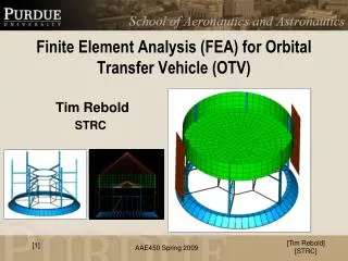
Support structure for Orbital Transfer Vehicle (OTV) Tim Rebold STRC [1] [Tim Rebold] [STRC]
Propulsion System Support Structure PPU PSU Electronics Module m = 106 kg • Reduces cabling • Easier Integration • Easier Testing • Thermal balance issue Xenon Tank & Propellant m = 1.6 kg Longer cabling Plumbing / Valves / Etc. *Not to scale **Contingency mass unrepresented Thruster m = 5.7 kg [Tim Rebold] [STRC] [2] • Truss / Frame • Statically determinate • Less members , less complex • More efficient (mass savings) • Only carry axial loads • Hard to realize • Joints need to carry predicted bending & shear • Loads (launch) are evenly distributed
OTV Configuration Lander Electronics Module A • Conclusions • Primary Mass:31 kg • Support Mass: 15.24 kg • Minert budget: <3.76 kg • finert = 0.3 A Propulsion System & Support Structure *Not to scale [Tim Rebold] [STRC] [3] • Goals • Center of Mass (CM) as close to aft (base) of spacecraft (s/c) • Design truss efficiently to minimize mass • Factor of Safety = 1.5
References [Tim Rebold] [STRC] [4] (1) Delta II Payload Planners Guide http://snebulos.mit.edu/projects/reference/launch_vehicles/Delta/DELTA_II_User_Guide_Update_0103.pdf (2) Skullney, W.E. Fundamentals of Space Systems. 2nd Edition. Ch. 8, pp.465-564 Oxford University Press, 2005. (3) “Properties of Materials.” 2009. Purdue University. http://www.lib.purdue.edu/eresources/wts/result.html?WTSAppName=Lib_edupackk (4) Sun, C.T. Mechanics of Aircraft Structures. New York: John Wiley and Sons, 2006. (5) Dnepr User’s Guide http://snebulos.mit.edu/projects/reference/launch_vehicles/DNEPR/Dnepr_User_Guide.pdf (6) Larson, W.J. Spacecraft Structures and Mechanisms. Microcosm, Inc. , 1995
Future Work [Tim Rebold] [STRC] [5] • Mount Solar Arrays, Reaction Control Wheels, Antenna, and Thermal components into OTV • Matlab script • Read data from Excel spreadsheet to calculate entire OTV (with payload) CM, and inertia matrix (about CM coordinates) in stowed (launch) and deployed (trans-lunar) stages • FEM analysis • Obtain better approximation of CM and inertia values • Perform modal analysis to see if OTV meets stiffness requirements placed on launch vehicle payloads
OTV CM Tracker - Current Best Estimate (Axial) • Acronyms • PPU: Power Processing Unit • PSU: Power Supply Unit • RCS: Reaction Control System Lander, 1.75 m, 220 kg MOTV = 550 kg CM = 1.056 m • Electronics Module, 1.25m, 24.3 kg • PPU • PSU x 1.5 m Structural / Thermal Control, 0.75 m, 110.88 kg 1 m Xenon Tank & Propellant, 0.685 m, 106 kg Solar Arrays, 0.50 m, 13.3 kg Feed system & Contingency Mass, 0.45 m, 4.7 kg 0 m Electric Propulsion Thruster, 0.10 m, 5.7 kg RCS Wheels, 0.05 m, 6 kg *Not to scale Antenna / Mount, 0 m, 9.12 kg [Tim Rebold] [STRC] [6]
Truss Configuration – 2D Planar F1y Aluminum 7075-T6 material selected for all structural elements R2x 4 F1x Stability Criterion 4 joints (j) 4 Reaction DOF’s (r)* 4 members (m) 2j = m + r 8 = 8 Distributed forces from propulsion system through launch 2 3 R1y F2x R1x 1 *4th reaction DOF not utilized for given applied loads F2y [Tim Rebold] [STRC] [7]
Support Structure Analysis Summary h t b [Tim Rebold] [STRC] [8]
Dimensions Electronics Module PPU PSU 0.320 m 0.7950 m 0.236 m φ = 0.470 m 0.9350 m 0.5 m 1.03 m 0.2 m *Not to scale [Tim Rebold] [STRC] [9]
Tank Mounting Flange Bolted Attachment Tank Support - Equatorial Mount Support Structure Xenon Tank To avoid high shell stresses, introduce loads tangentially to tank surface rather than radially *Figure based from Reference 6 [10] [Tim Rebold] [STRC]