Download
1 / 48
480 likes | 651 Vues
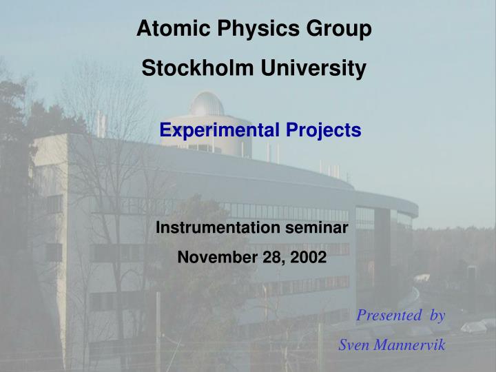
Atomic Physics Group Stockholm University. Experimental Projects. Instrumentation seminar November 28, 2002. Presented by Sven Mannervik. Experimental work is primarily performed at the Manne Siegbahn Laboratory National Facility at Stockholm University. G. A,E: Laser spectroscopy

E N D
Atomic Physics Group Stockholm University Experimental Projects Instrumentation seminar November 28, 2002 Presented by Sven Mannervik
Experimental work is primarily performed at the Manne Siegbahn Laboratory National Facility at Stockholm University
G A,E: Laser spectroscopy B,G: Atomic collision C: Ion- surface collision D: Mass measurements F: Ion-electron recombination
We use beams of highly charged ions from the electron beam ion source (EBIS) , the ECR ion source and stored ions in a synchrotron ion-cooler storage ring (CRYRING). • In the ring we perform experiments with cooled stored ions • on electron-ion recombination and laser assisted excitation and recombination • on fast atomic collisions (single and multiple electron capture, ionization, recoil momentum spectroscopy) with internal target. • on laser spectroscopy, and lifetime measurements of metastable states at stored heavy ions. • With slow highly charged ions we study: • surface and cluster interactions • multiple electron transfer reactions • mass spectrometry of highly charged ions in a Penning trap
Excited state Aik Metastable state Allowed transition A=108 s-1 Forbidden transition A=1 s-1 Lifetime measurements The radiative lifetime (t) is determined by the sum of the transition probabilities (Aik) for all decay channels t = S 1/ Aik Why are radiative lifetimes needed? Intensity I=NiAik
5 mm fast ion beam Laser 500 km ! A=1 s-1 A=108 s-1 Why stored ion beam? • High spectral resolution (laser) • Time-resolution and long observation time • Pure light source (isotope separation) • Ultra high vacuum
passive method M obs G PM Observation of spontaneous decay E laser obs M G PM Laser Instead of the passive method we use the active laser probing method forbiddenline Probing of the meta- stable population by laser excitation + higher efficiency + high selectivity + high flexibility We gain a factor of 5000 and can reduce detector background.
Lifetime: Ca+ 3d 2D3/2 moving laser probe pulse Laser probing technique (LPT) developed at CRYRING for lifetime measurements Shutter synchronized with the ring creates laser pulses at variable time delays
Photon counts Laser light Higher level Lifetime curve Fluorescence Time Metastable level Moving probe pulse Lower level cycle 1 cycle 2 Number of injected ions has to be constant! Photomultiplier cycle 3 Laser pulses Laser CRYRING Fluorescence yield Time after injection Laser probing technique – in summary
The FERRUM project Eta Carinae blob 62 metastable levels z6D7/2 Laser probing of a 6S 5/2 6516 Å a6S5/2 1/2 3/2 5/2 7/2 9/2 a6DJ
Results Fe II Rostohar et al Phys Rev Lett 86(2001)1466
34 metastable levels c 2D3/2 Long lifetime – very sensistive to corrections b 4P5/2 Ground level a 4F3/2 Preliminary 27 10 s Experimental results Ti II c 2D3/2 : 0.35 0.05 s
Dn=200 MHz Laser and Radio-Frequency double resonance spectroscopy Ion beam Dn<1 MHz Laser beam Collinear geometry gives subDoppler line width
cooling SBD recombination Electron Cooler Dipole Magnet Ion-electron interaction
Radiative Recombination is an direct spontaneous process in which a continuum electron is captured with the subsequent release of a photon Recombination Overview Dielectronic Recombination is a resonant process in which a continuum electron is captured as it excites a target electron, forming a short lived intermediate state which decays by photon emission
SBD Electron Cooler Dipole Magnet Experiment CRYRING
Used for radiative recombination studies of ions with free electrons at CRYRING Influence of external (electromagnetic) fields on recombination rate B Si14+ Si14+ He++ Laser induced recombination into specific quantum states enhancement factor 200 10-6 10-4 10-2 100 Energy (eV) E E p+e- H(n=3)
AC SBD Electron Cooler Dipole Magnet FS2 FS1 PC WP Nd:YAG Laser 2nd harmonic HVP PD1 PD2 Excimer-dye laser Laser Ring with an Implemented Amplifier The optical laser ring with the implemented amplifier gives a total gainof about 23 in comparison with a single passage of the pulse through the interaction zone. T. Mohamed, G. Andler, R. Schuch, subm. to J. Opt. Com.
Dielectronic recombination (DR) process ‘allowed’ process C3+ + e C2+ 1s22p4f3Ge 1s22sg 3Ge e- Coulomb interaction ‘forbidden’ process First ionization limit 1s22sf 1Fo 1s22p4d3Do e- Spin-orbit interaction Ionization limit Radiative stabilization 1s22p3d 3Fo 1s22p23P
Importance of knowing the ring length Relative position • S6 • Beam profile monitor • Two cooler scrapers Absolute length • Laser induced recombination • Measurement of the difference between DR resonances
15 l QED effects are small for high-n, so these states can be calculated accurately Exp. Uncertainty Theory Uncertainty 2p1/2 2s We are now doing…“Quantum electrodynamics in the dark” Physics World, Aug. 2001 Li-like Kr Madzunkov et al., Phys. Rev. A65, 032505 (2002) 71.243(8) 71.248(19) Energy Splitting
Ni17+ + e Ni16+
Fast ion-atom collisions Transfer Ionization in MeV p-He Collisions Studied by Pulsed Recoil-Ion-Momentum Spectroscopy in a Storage Ring/Gas Target Experiment p-HeH0+He2++e- at 2.5-4.5 MeV
CRYRING:High Current (100 A H+)Cold and narrow beam ( 1 mm) PROJECTILE DETECTOR GAS TARGET Ring beam Gas jet pR║ Fast Ion-Atom collisions in CRYRING • The Gas-Jet Target: • Density: up to 1011 cm-3 • Jet diameter: 1.0 mm • Luminosity: • 61024 cm-2s-1. • TI-rate @ 4.5 MeV: • 1 min-1. • SI-rate @ 4.5 MeV: • 107 s-1.
He p v 0.55 mrad The He nucleus is not directly involved in the collision v pR0 v RIMS! Kinematical capture through momentum overlap. p e- H v v He He2+ pR-Q/vp-mevp/2 The He nucleus is emitted in the backward direction as a result of the kinematical capture. Shake-off o 45 2 v Transfer Ionization in fast H+-He collisions: Thomas p-e-e scattering Kinematical Transfer Ionization (KTI) pR=5.0 au @ 2.5 MeV (ER~50 meV)
KTI/(SC+TI) [%]
q+ e- e- e- Slow Highly Charged Ions Colliding with C60 – stability and fragmentation
Collimated C60 Jet Cylindrical analyzer T=500 C Aq+ Vex 0 V TRIG -100 V Time-of-flight (q-s)+ START PSD STOP Multi-hit TDC PSD C60 C604+ C605+ 29+ 28+ 27+ C603+ Xe30+ + C60 C606+ Aq+ Xe28 ++ …. C607+ Time-of-flight Experimental set-up
26 keV Ar8+ + C60 Ar(8-s)+ + ... s = 1 s = 2 Cold s = 3 s = 4 Hot
Decay channels of excited C60: Evaporation of small neutral fragments (C60r+)*C60-2mr++ C2m (m=1,2,3,4…) Activation energy Ea for evaporation of a C2 unit ~10 eV dominate for r 3 Asymmetric fission U(R) (C60r+)*C60-2m(r-1)++ C2m+(m=1,2,3,4…) Bfis dominate for r 4 Ekin C60r+ Decay rate: k 1/exp( Bfis / kBT) C58(r-1)+ + C2+ R Depends on internal energy or temperature of C60 decrease T increase lifetime kinetic energy releases fission barriers stability Multifragmentation: (C60r+)*many small fragments in low charge states
Storage and lifetime measurements of C60 ions using ConeTrap: An Electrostatic Ion Trap for Atomic and Molecular Physics -electrostatic 8 mm -simple -small -easy to cool 175 mm H.T. Schmidt, H. Cederquist, J. Jensen, and A. Fardi, NIMB 173, 523 (2001).
Mass determinations with highly charged ions relevant for fundamental physics SMILE Trap Ions from CRYSIS
How to measure atomic mass with very high precision? n- 810 Hz n+ 36 MHz nz 240 kHz • Principle : Measurement of the cyclotron frequency of an ion trapped in a homogeneous magnetic field : using HCI the precision increases linearly
Frequency Detection • nc is scanned and the ion TOF is measured • A resonance is detected :Relative uncertainty = 0.57 ppb • To avoid the B dependence the unknown mass is deduced from the ratio: • The atomic mass m is obtained by correcting for the missing q electrons and binding energies the reference ion is 12Cq+ or H2+
… a relative mass accuracy of dm/m = 10-9-10-10 is required Where does the mass of an atom or ion matter • 28Si for Atomically Defined Kilogram Mass Standard • 76Ge an 76Se gives the Q value for the neutrino-less double beta decay • 133Cs, for Accurate Determinations of the Fine Structure Constant • 24Mg and 26Mg for bound-electron g factor determination in hydrogen-like ions • 198-204Hg to solve the “mercury problem” in Audi/Wapstras mass table • binding energies from Aq+, Aq-1, Aq-2 ...
ECR – a new ion source medium high charge state on high voltage platform
Pb55+ on Ta: Rc72 a.u. nc 53 Filling and cascading mechanism ? How fast charge-state equilibrium reached? Time until hollow atom is relaxed ? Auger transitions X-ray transitions 8.5 q keV Pb55+: t6 fs Side-feeding
Below surface relaxation ?Auger and X-ray spectroscopy, transmission exp • -Above surface relaxation ? Grazing Angle Scattering Neutralization Charge State Distribution Energy loss Large angle Scattering Arq+ Au(111) X-ray Measurement Pbq+ Ta Absorption Method
dFront dBack 8.5 q keV Pb53+ Mean Emission Depth 44 nm (about 100 monolayers) Left Si(Li) detector Ion beam Ta foil Focusing system Right Si(Li) detector Moveable Faraday cup Below surface relaxation Foil thickness determined by Rutherford backscattering technique