Download
1 / 24
240 likes | 488 Vues
MICRO PROCESSER. The micro processer is a multipurpose programmable, clock driven, register based, electronic integrated device that has computing and decision making capability .

E N D
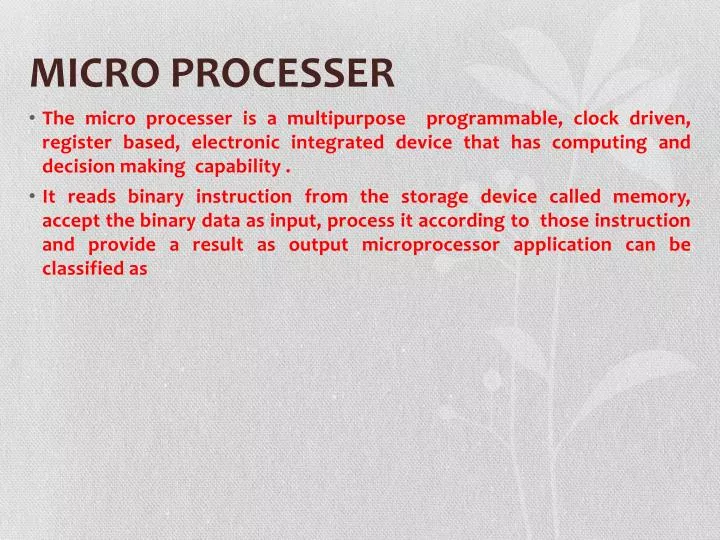
MICRO PROCESSER • The micro processer is a multipurpose programmable, clock driven, register based, electronic integrated device that has computing and decision making capability . • It reads binary instruction from the storage device called memory, accept the binary data as input, process it according to those instruction and provide a result as output microprocessor application can be classified as
Re- programmable system Embedded system
Micro processer communicates and operates in the binary numbers 0 and 1 called bits. Each microprocessor has a fixed set of instructions in the forms of binary patterns called machine language.
BLOCK DIAGRAM OF MICROPRECESSOR REGISTER MEMORY ALU CONTROL UNIT
MICRO COMPUTER • It is a small computer that contain microprocessor. In microcomputer cup is single integrated circuit called microprocessor
BLOCK DIAGRAM OF MICROCOMPUTER Address bus Control Control Bus Bus Address bus Input Devices I/O Port Memory (RAM/ROM) CPU Output Devices
MICRO CONTROLOR • It is a small computer • One chip RAM, ROM, I/O port • E.g. Intel 8051, PIC16x CPU RAM ROM I/O port Timer Serial Comport
MEMORY • It consist of mixture of RAM and ROM. It may also have magnetic hard disk or pen drive it’s function are • Store the binary code for the sequence of instruction and then write a program from that sequence of instruction for the computer. • Store the binary coded data with which computer is going to work.
CENTRAL PROCESSING UNIT • The CPU control the operation of computer CPU fetches binary coded instruction from memory. Decode the instruction in to a series of action and carries out these action in a sequence of steps. • It also contains the instruction pointer register which hold the address of the next instruction or data item to be fetch from memory
ADDRESS BUS • Address bus of 16,20,24 or 32 parallel signal line on these lines CPU sends out the address of the memory location to be written to or from
DATA BUS • The data bus consist of 8, 16 or 32 parallel lines and are bidirectional that CPU can read data in from memory and send data out of memory on the lines
CONTROL BUS • The control bus consist of 4 to 10 parallel signal lines. The CPU send out signal on the control bus . To enable the I/O of the address memory device. Control bus signal are memory read, write ,I/O read, I/o write.
VON NEUMANN ARCHITECTURE Output Input Control Unit ALU Main Memory
According to Von Neumann architecture the input device, output device and Processer are separated from each other so that they could function correctly independently but joined with each other through Bus. The memory of Von Neumann machine consist of thousand storage location called word of 40 binary digit both data and instruction are stored in the ALU perform arithmetical as well as logical operation.
MICROPROCESSOR I/O ALU REGISTER SYSTEM BUS CONTROL UNIT Memory RAM ROM Fig:- microprocessor based system with bus architecture
It include three components: microprocessor, i/o(input/output) and memory. These component are organized around common communication path called bus. The entire group of components is also referred to as sub-system. The microprocessor is the component of microcomputer.
Interrupt signal SID SOD Interrupt control Serial I/O control 8-bit internal Bus B C Temp Register Status Flag Accumulator D E H L Static pointer Program counter Increment/decrement address latch ADDRESS BUFFER Data/Address Buffer A8-A15 Address bus AD0-AD7 Add/data Bus
8085 PROGRAMMING MODEL The model is a conceptual representation of and real object Accumulator 16- bit address bus ALU Rsgister Flags 8-bit data bus Memory Pointer register Instructions decoder Control signal Timing and control unit
8085 hardware model Accumulator A (8- bit) Flag Register B (8-bit) C (8-bit) D (8-bit) E (8-bit) H (8-bit) L (8- bit) Stack Pointer (SP) Program counter (PC) data bus Address bus
The 8085 hardware model shows two major part in one part contains 8-bit register called Accumulator, Arithmetic and logical unit(ALU), which perform arithmetic and logical operations, flags, and instruction decoder. In other part contains 16- bit register and memory pointer register. They are connected each other with the help of internal buses. The arithmetic and logical operation are performed in ALU and result are stored in Accumulator. The flag contains Flip-Flop which reflect the result by it’s set and reset state. It also contains unidirectional 16-bit address bus which passes the memory address. It also consist 8-bit data bus which transfer data and control signals are passed through control bus.
Instruction and data type • An instruction is the set of command to microprocessor which perform given task on given data. Each instruction has two parts they are, operation(task) to be perform called operation code (opcode) and data to be operated called operand. Data is specifies in various ways such as 8-bit or 16-bit data, a register or internal memory address and 8-bit or 16-bit address. 8085 instruction set are classified into three type according to there word size. • One word one byte instruction • Two word two byte instruction • Three word three byte instruction
One byte one word instruction • It specifies the opcode and operand in single word for example