Download
1 / 29
511 likes | 1.28k Vues
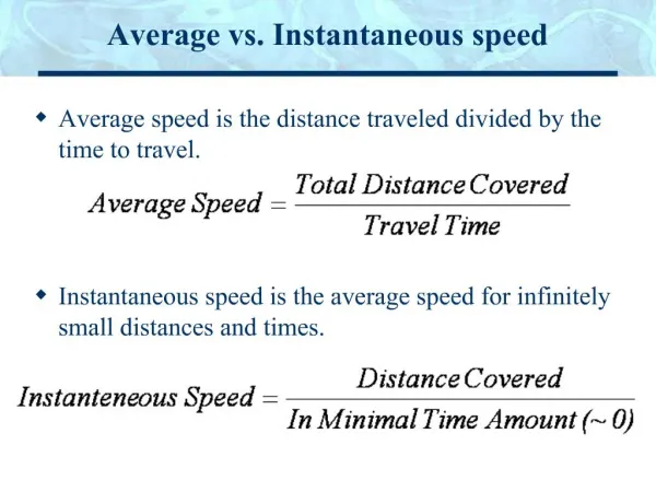
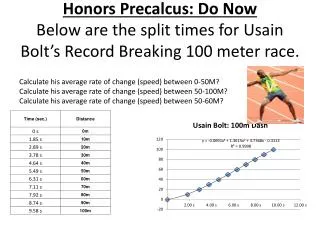
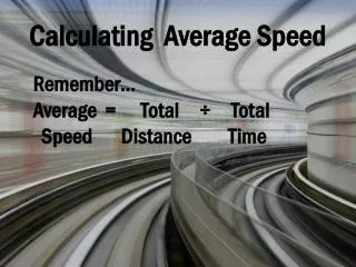
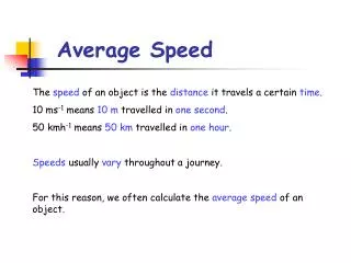
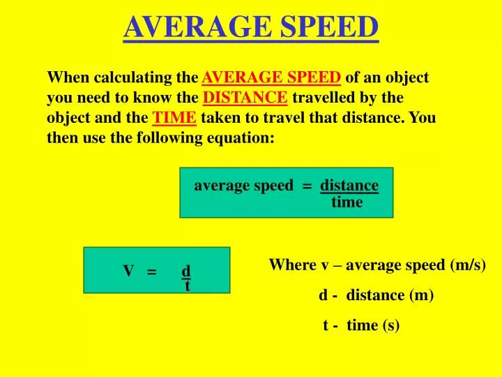
AVERAGE SPEED. When calculating the AVERAGE SPEED of an object you need to know the DISTANCE travelled by the object and the TIME taken to travel that distance. You then use the following equation:. average speed = distance. time. V = d. Where v – average speed (m/s)

E N D
AVERAGE SPEED When calculating the AVERAGE SPEED of an object you need to know the DISTANCE travelled by the object and the TIME taken to travel that distance. You then use the following equation: average speed = distance time V = d Where v – average speed (m/s) d - distance (m) t - time (s) t
L.I: To calculate the average speed of a trolley on a slope APPARATUS: slope, trolley, timer,meter stick METHOD: measure distance on slope release trolley and start timer together stop timer when trolley reaches 2m mark. complete table. RESULTS:
SPEED OF SOUND LEARNINGINTENTION To calculate the speed of sound experimentally. APPARATUS fast timer,2 microphones,metre stick METHOD Place the 2 microphones 1m apart. Switch on timer. Clap hands above start microphone. Record time in table. Repeat twice more. Calculate average time using v = d/t. RESULTS CONCLUSION Speed of sound equals 340m/s.
SOUND AND LIGHT The speed of light is much faster than the speed of sound. Think of a thunder storm. You see the lightning then you hear the thunder. This is because the light reaches us almost immediately. The values we need to know are: Speed of sound = 340m/s Speed of light = 300000000m/s The equation we use is: Distance = speed x time d = v t d v t
MORSE CODE In 1836, Samuel Morse demonstrated the ability of a telegraph system to transmit information over wires. The information was sent as a series of electrical signals. Short signals are referred to as dits (represented as dots). Long signals are referred to as dahs (represented as dashes). With the advent of radio communications, an international version of Morse code became widely used.
TELEPHONE The most common method of communicating with wires is the telephone. The TRANSMITTER (mouthpiece) contains a MICROPHONE which changes sound energy to electrical energy. The RECEIVER(ear piece) contains a loudspeaker that changes electrical energy into sound energy.
SOUND SIGNALS Sound signals are transmitted down wire at almost 300000000 m/s (speed of light) and the signals can be displayed using an oscilloscope as shown:
WAVES Messages can be sent from one place to another by using waves. They are sent from a transmitter to a receiver. You will have heard of radio, tv and microwaves. A typical wave pattern is shown below:
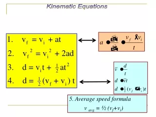
SPEED OF A WAVE To calculate the speed of a wave we use the equation: V = f x v f Where v = velocity (m/s) f = frequency (Hz) = wavelength (m)
WAVE DEFINITIONS Frequency: The number of complete waves that pass a point every second. Symbol f, units – hertz (hz). Wavelength: The distance from a point on a wave to the next similar point – from crest to crest. Symbol (lambda), units - metres (m). Wave speed: The distance a wave travels each second. Symbol v, units – metres per second (m/s) Amplitude: The maximum height of the wave above or below the zero line. Units – metres (m).
RADIO Transmitter mast Old fashioned receiver Radio signals are waves that transfer energy. They are sent from a transmitter at a speed of 300000000m/s and picked up by a receiver. Wires are not needed between the transmitter and the receiver.
RADIO TRANSMITTER Radio frequency Modulator Amplifier Aerial Audio frequency Modulator: combines the 2 electrical signals Amplifier: makes the combined signal bigger Aerial: changes electrical signal into a radio wave and sends them in all directions.
RADIO RECEIVER Aerial Tuner Decoder Amplifier Loudspeaker Power supply Aerial: Picks up all radio waves. Tuner: Selects the frequency you want. Decoder: Separates the radio wave from the sound wave. Amplifier: Makes the weak signal stronger. Power supply: Needed for amplifier. Loudspeaker: Changes electrical signal to sound.
SOUND TELEVISION RECEIVER Decoder Amplifier Loudspeaker Aerial Tuner Decoder Amplifier Tube VISION Aerial: Picks up all wave energy. Tuner: Selects the TV frequency you want. SOUND VISION Decoder: Selects the sound signal Decoder: Selects the picture from wave. signal from wave. Amplifier: Makes the sound signal Amplifier: Makes the picture stronger. signal stronger Loudspeaker: Changes electrical TV Tube: Changes electrical signal to sound. signal to light
TV TRANSMITTER High frequency signal Modulator Amplifier Audio signal Aerial High frequency signal Modulator Amplifier Camera (video) Modulator: combines high frequency signals with audio and video signals. Amplifier: electrical signals are made stronger. Aerial: signals are changed to TV and radio waves.
TV TUBE & LINE BUILD UP A tv picture is built up by a series of lines. An electron beam scans across the television tube (electromagnetic deflection). A special coating gives out light when the beam passes over it. The beam starts at the top then scans backwards and forwards till it reaches the bottom. There are 625 lines for one picture and 25 pictures per second.
COLOUR TV In a colour tv there are three electron guns. There are three colours of light given out by the fluorescent paint on screen. These are red, green and blue. All colours can be made by mixing these three :- yellow - red & green magenta - red & blue cyan - green & blue white - red, blue & green
AMPLITUDE MODULATION Amplitude modulation is a way of varying the amplitude of a high frequency radio wave so that it carries a low frequency audio wave Low frequency audio wave Carrier wave Amplitude modulated wave
AM WAVE FM WAVE
DIFFRACTION LEARNING INTENTION Waves with a long wavelength can bend round or over obstacles much better than short wavelengths. SHORT WAVELENGTH LONG WAVELENGTH Radio waves have a longer wavelength than TV waves. This is why in some hilly regions you can receive good radio reception but not a good tv picture.
LAW OF REFLECTION LEARNINGINTENTION To investigate the relationship between the angle of incidence and the angle of reflection for a plane mirror. APPARATUS Power supply, ray box, mirror, single-slit and a protractor. INSTRUCTIONS Mirror 80o 60o 30o N 10o
RESULTS CONCLUSION The angle of reflection is equal to the angle of incidence.
OPTICAL FIBRES • An optical fibre is a thin piece of glass. • Optical fibres are used in some telecommunication systems. They are used to transmit light signals. • Signal transmission along an optical fibre takes place at a speed of 200 000 000m/s
OPTICAL FIBRES 2 cont. • The transmission of the light signal along an optical fibre works by reflection inside the fibre. • Many telecommunication links into the home, like cable TV, use optical fibres. • Fibre optics are cheaper than copper cables, however, they are difficult to join together.
TOTAL INTERNAL REFLECTION LEARNING To find out about TOTAL INTERNAL INTENTION: REFLECTION. APPARATUS: Ray box, single slit, semi-circular block & protractor METHOD: Set up apparatus as shown. Send a single beam along 20o line. Draw path of ray. Repeat for an angle of 60o Complete table. 60o 20o Ray box RESULTS
CONCLUSION: When no light passes from the perspex to the air, we have TOTAL INTERNALREFLECTION taking place
SATELLITES • Satellites are used to send information from one part of the world to the other. • A geostationary satellite is one that stays above the same point on the earth’s surface (36000km). • Curved reflectors on receiving aerials make the signals stronger. • The curved reflectors gather the signals and reflect them to a focus which makes them stronger.
CURVED REFLECTORS Learning Intention: How curved reflectors make signals stronger RAYBOX