Download
1 / 15
160 likes | 472 Vues
Unit 27 Single-Phase Transformers. Objectives: Discuss the different types of transformers. List transformer symbols and formulas. Discuss polarity markings. Unit 27 Single-Phase Transformers. A transformer is a magnetically operated machine.

E N D
Unit 27 Single-Phase Transformers Objectives: • Discuss the different types of transformers. • List transformer symbols and formulas. • Discuss polarity markings.
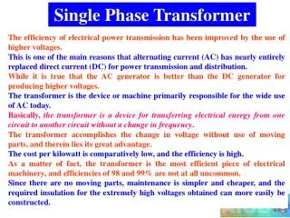
Unit 27 Single-Phase Transformers • A transformer is a magnetically operated machine. • All values of a transformer are proportional to its turns ratio.
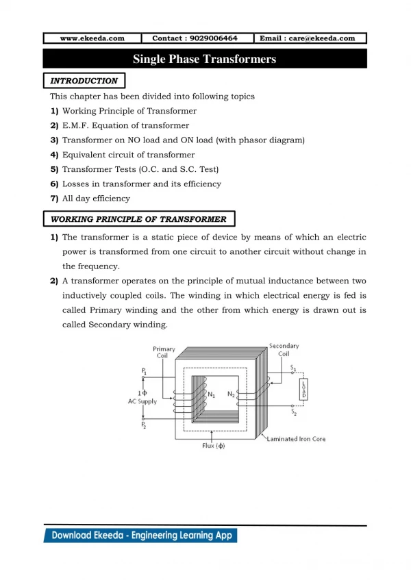
Unit 27 Single-Phase Transformers • The primary winding is connected to the incoming power supply. • The secondary winding is connected to the driven load.
Unit 27 Single-Phase Transformers • This is an isolation transformer. The secondary winding is physically and electrically isolated from the primary winding.
Unit 27 Single-Phase Transformers • The two windings of an isolation transformer are linked together by the magnetic field.
Unit 27 Single-Phase Transformers • The isolation transformer greatly reduces voltage spikes.
Unit 27 Single-Phase Transformers • Basic construction of an isolation transformer.
Unit 27 Single-Phase Transformers • Each set of windings (primary and secondary) is formed from loops of wire wrapped around the core. • Each loop of wire is called a turn. • The ratio of the primary and secondary voltages is determined by the ratio of the number of turns in the primary and secondary windings. • The volts-per-turn ratio is the same on both the primary and secondary windings.
Unit 27 Single-Phase Transformers Transformer Symbols NP = number of turns in the primary NS = number of turns in the secondary EP = voltage of the primary ES = voltage of the secondary IP = current in the primary IS = current in the secondary
Unit 27 Single-Phase Transformers Transformer Formulas EP / ES = NP / NS EP x NS = ES x NP EP x IP = ES x IS NP x IP = NS x IS
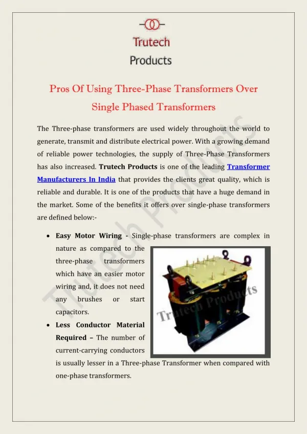
Unit 27 Single-Phase Transformers • The distribution transformer is a common type of isolation transformer. This transformer changes the high voltage from the power company to the common 240/120 V.
Unit 27 Single-Phase Transformers • The control transformer is another common type of isolation transformer. This transformer reduces high voltage to the value needed by control circuits.
Unit 27 Single-Phase Transformers • Polarity dots are placed on transformer schematics to indicate points that have the same polarity at the same time.
Unit 27 Single-Phase Transformers Review: • All values of voltage, current, and impedance in a transformer are proportional to the turns ratio. • The primary winding of a transformer is connected to the source voltage. • The secondary winding is connected to the load.
Unit 27 Single-Phase Transformers Review: • An isolation transformer has its primary and secondary voltage electrically and mechanically separated. • Isolation transformers help filter voltage and current spikes. • Polarity dots are often added to schematic diagrams to indicate transformer polarity.