Download
1 / 15
150 likes | 270 Vues
Flowing Liquid Lithium Limiter for HT-7. Utilizing TEMHD to maintain a clean Li surface, keep it below 400C, and prevent ejection. Conceptual Design. Heat flux. Hot. Li flow. Cooling channels. Inlet. Outlet. Lithium reservoir.

E N D
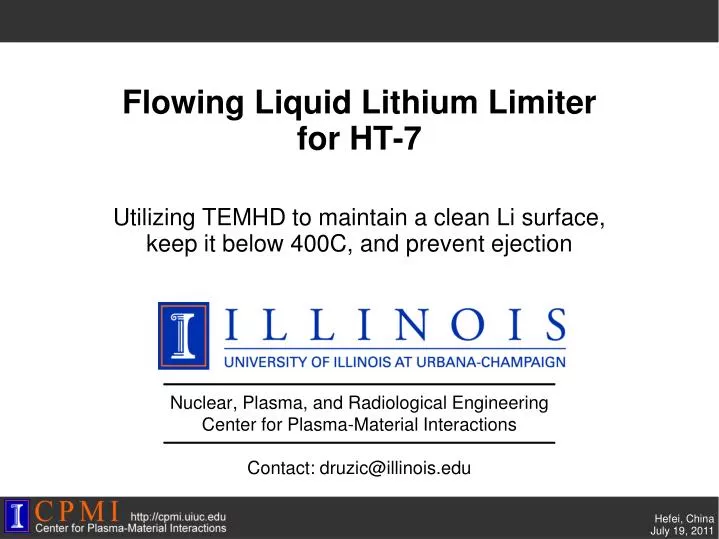
Flowing Liquid Lithium Limiterfor HT-7 Utilizing TEMHD to maintain a clean Li surface, keep it below 400C, and prevent ejection
Conceptual Design Heat flux Hot Li flow Cooling channels Inlet Outlet Lithium reservoir • To flow against a high field one needs to maintain the temperature gradient even outside of the plasma heat flux zone. • How: utilize TEMHD in the return flow legs too: • In a limiter machine such as HT-7, this is easier since there is some heat flux along the entire plasma-facing surface. B J J J Hot, passively (not cooled) or heated
Velocity and temperature gradient • Average velocity of liquid lithium in the trench • The power transferred by the trench structure is written as • The temperature gradient can be calculated through
Top surface temperature and flow velocity for SLiDE • SLiDE’s geometric parameters are used here. Heat flux is 4MW/m^2 (typical value for our experiment, corresponding to 1500W e-beam power) . • Top surface temperature increases with the magnetic field and flow velocity decreases with the magnetic field after 0.01T (100Gauss). This model fits our experimental results
Apply to HT-7 to find parameters for the trench • Top surface temperature and flow velocity change (from previous equations). • heat flux (6MW/m^2), toroidal magnetic field (2T), the length of direct heating area along radius direction (80mm), the length of hot region along a single trench (L1) (110mm) and the length of cool region (L2) (30mm). • F. Gao et al, Fusion Eng. Design 83 (2008) 1–5 • Q. Li et al, Fusion Eng. Design85 (2010) 126–129
Estimate top surface temperature and flow velocity • Top surface temperature is 396C and flow velocity is 0.36m/s. • Bottom of trench is assumed to be kept at 200C.
Pressure drop in return flow • The pressure drop equation • Here Ha is the Hartmann number. • C is the conduction ratio. • is the electrical conductivity of lithium. is the electrical conductivity of the wall material. t is the thickness of SS wall(1.5mm) and w is the width of the liquid lithium flow (5mm). is the density; is the dynamic viscosity; u is the entering flow velocity (about 0.36m/s) and L is the length of the flow (0.13m). • The pressure drop is about 3.6*10^5 Pa. • However if the wall is insulated C is almost infinity. Since Ha is 837 pressure drop becomes which is 427Pa. • L.Barleon, Fusion Eng. Design 14(1991) 401-412
Ejection problem • Critical temperature gradient along the lithium surface is • Here is the standard gravity. P is the thermoelectric power (Seebeck coefficient of Li). is the surface tension (0.32N/m at 250C). R is the radius of the ejected droplet and the largest should be half of the width of the lithium trench (1mm). • Resulting critical temperature gradient is 11039 C/m. If the surface temperature gradient is lower than this value there is no ejection. The temperature gradient along the top surface needs modeling but since this value means 200C difference within 2cm the real temperature gradient may be lower than this. • However the incoming current from the plasma is also important for the ejection problem. (need those values for the calculation.) • M.A. Jaworski, Macroscopic motion of liquid metal plasma facing components in a diverted plasma, Journal of Nuclear Materials, In Press, DOI: 10.1016/j.jnucmat.2010.10.074.
LiMIT design for HT-7 limiter • 3 parts: trench, tray and heat sink • Trench and tray are made of stainless steel (SS316) and the heat sink is made of copper. • This limiter is 134mm*254mm*28mm. • The heat sink needs cooling.
Trench Front Back
Trench • Trench is 130mm*250mm*6.5mm. Thickness of the SS wall is 0.5mm and width of the lithium trench is 2mm. Height of the trench is 5mm. The thickness between the bottom surface of the trench and the bottom of each channel is 1.5mm (the bottom plate under those fan structure). • Both ends of the bottom plate is cut to let lithium flow into the back flow channel (10mm on each side). Minimize the area of free surface to lower the ejection. • The top surface of the trench is as high as the edge of the tray. The distance between the bottom surface of the trench and the tray is 5mm. (for back flow)
Tray • Wall thickness is 2mm. The edge is round shapebecause of the parallel heat flux. (I’m not sure if this is enough since the toroidal parallel heat flux is a major component of the total heat flux for limiter structure.) • Height of the tray is 11.5mm. Thickness of the bottom is 1.5mm.
Engineering Details • Will follow based on remainder of visit and detailed consultation with HT-7 staff.