Download
1 / 77
921 likes | 1.45k Vues
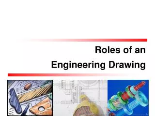
Chapter 1 Overview of an Engineering Drawing. Graphics language. Engineering drawing. Projection methods. Orthographic projection. Drawing standards. TOPICS. Traditional Drawing Tools. Lettering. Freehand Sketching. TOPICS. GRAPHICS LANGUAGE. Effectiveness of Graphics Language.

E N D
Chapter 1 Overview of an Engineering Drawing
Graphics language Engineering drawing Projection methods Orthographic projection Drawing standards TOPICS
Traditional Drawing Tools Lettering Freehand Sketching TOPICS
Effectiveness of Graphics Language 1. Try to write a description of this object. 2. Test your written description by having someone attempt to make a sketch from your description. You can easily understand that … The word languages are inadequate for describing the size, shape and featurescompletely as well as concisely.
The language is known as “drawing” or “drafting” . A drawing can be done using freehand, instrumentsor computermethods. Composition of Graphic Language Graphic languagein “engineering application” use linesto represent the surfaces, edges and contoursof objects.
Example Freehand drawing The lines are sketched without using instruments other than pencils and erasers.
Example Instrument drawing Instruments are used to draw straight lines, circles, and curves concisely and accurately. Thus, the drawings are usually made to scale.
Example Computer drawing The drawings are usually made by commercial software such as AutoCAD, solid works etc.
Graphics language Describe a shape(mainly). Word language Describe size, location andspecification of the object. Elements of Engineering Drawing Engineering drawing are made up of graphics language and word language.
Geometric construction Line types Projection method Lettering Basic Knowledge for Drafting Word language Graphics language
Perspective Parallel Oblique Orthographic Axonometric Multiview PROJECTION METHOD
The projection theory is used to graphically represent 3-D objects on 2-D media (paper, computer screen). The projection theory is based on two variables: 1) Line of sight 2) Plane of projection (image plane or picture plane) PROJECTION THEORY
There are 2 types of LOS : Line of sight Line of sight Line of sightis an imaginary ray of light between an observer’s eye and an object. parallel converge and Parallel projection Perspective projection
The image is produced by connecting the points where the LOS pierce the projection plane. Plane of projection Plane of projection Plane of projectionis an imaginary flat plane which the image is created. Parallel projection Perspective projection
Disadvantage ofPerspective Projection Perspective projection is not used by engineer for manu- facturing of parts, because 1) It is difficult to create. 2) It does not reveal exact shape and size. Width is distorted
Object views from top 1 2 3 4 1 2 3 4 5 5 Projection plane MEANING Orthographic projectionis a parallel projection technique in which the parallel lines of sight are perpendicular to the projection plane
ORTHOGRAPHIC VIEW Orthographic view depends on relative position of the object to the line of sight. Rotate Two dimensions of an object is shown. Tilt More than one view is needed to represent the object. Multiview drawing Three dimensions of an object is shown. Axonometric drawing
Both drawing types are used in technical drawing for communication. ORTHOGRAPHIC VIEW NOTES Orthographic projection technique can produce either1. Multiview drawingthat each view show an object in two dimensions. 2. Axonometric drawingthat show all three dimensions of an object in one view.
Axonometric (Isometric) Drawing Advantage Easy to understand Disadvantage Shape and angle distortion Example Distortions of shape and size in isometric drawing Circular hole becomes ellipse. Right angle becomes obtuse angle.
Multiview Drawing Advantage It represents accurate shape and size. Disadvantage Require practice in writing and reading. Example Multiviews drawing (2-view drawing)
Drawing standards are used so that drawings convey the same meaning to everyone who reads them. Introduction Standards are set of rules that govern how technicaldrawings are represented.
Full name Country Code USA American National Standard Institute ANSI Japanese Industrial Standard Japan JIS British Standard UK BS Australian Standard Australia AS Deutsches Institut fürNormung Germany DIN International Standards Organization ISO Standard Code
Contents Code number Partial List of Drawing Standards JIS Z 8311 Sizes and Format of Drawings JIS Z 8312 Line Conventions JIS Z 8313 Lettering JIS Z 8314 Scales JIS Z 8315 Projection methods JIS Z 8316 Presentation of Views and Sections JIS Z 8317 Dimensioning
Drawing Sheet A4 Trimmed paper of a size A0 ~ A4. A3 Standard sheet size(JIS) A4 210 x 297 A3 297 x 420 A2 420 x 594 A1 594 x 841 A0 841 x 1189 A2 A1 (Dimensions in millimeters) A0
Orientation of drawing sheet c d d c c Sheet size c (min) d (min) A4 10 25 A3 10 25 A2 10 25 A1 20 25 A0 20 25 1. Type X (A0~A4) 2. Type Y (A4 only) Drawing space Drawing space Border lines Title block Title block
: Drawing Scales Length, size Scaleis the ratio of the linear dimension of an element of an object shown in the drawing to the real linear dimension of the same element of the object. Size in drawing Actual size
Designation of a scale consists of the word “SCALE” followed by the indication of its ratio, as follow Drawing Scales SCALE 1:1 for full size SCALE X:1 for enlargement scales SCALE 1:X for reduction scales
Continuous thick line Visible line Dimension line Extension line Leader line Continuous thin line Dash thick line Hidden line Chain thin line Center line Basic Line Types Name according to application Types of Lines Appearance NOTE : We will learn other types of line in later chapters.
Meaning of Lines Visible lines represent features that can be seen in the current view Hidden lines represent features that can not be seen in the current view Center linerepresents symmetry, path of motion, centers of circles, axis of axisymmetrical parts Dimension and Extension linesindicate the sizes and location of features on a drawing
DRAWING TOOLS 1. T-Square 2. Triangles
DRAWING TOOLS 2H or HB for thick line 4H for thin line 3. Adhesive Tape 4. Pencils
DRAWING TOOLS 5. Sandpaper 6. Compass
DRAWING TOOLS 7. Pencil Eraser 8. Erasing Shield
DRAWING TOOLS 9. Circle Template 10. Tissue paper
DRAWING TOOLS 11. Sharpener 12. Clean paper
ABCDEFGHIJKLMNOPQRSTUVWXYZABCDEFGHIJKLMNOPQRSTUVWXYZABCDEF Lettering ABCDEFGHIJKLMNOPQRSTUVWXYZABCDEFGHIJKLMNOPQRSTUVWXYZABCDEF
To communicate nongraphic information. As a substitute for graphic information, in those instance where text can communicate the needed information more clearly and quickly. - shape - space between letters and words Legibility - size- line thickness Uniformity Text on Drawings Text on engineering drawing is used : Thus, it must be written with
Dimension & Notes Title Block Notes Example Placement of the text on drawing
Use only a vertical Gothic text style. Use a Gothic text style, either inclined or vertical. Use both capital and lower-case letters. Use all capital letters. Use 3 mm for most text height. Same. For letters in title block it is recommend to use 5~8 mm text height Space between lines of text is at least 1/3 of text height. N/A.Follows ANSI rule. Lettering Standard ANSI Standard This course
Basic Strokes Straight Slanted Horizontal Curved Examples : Application of basic stroke 4 5 1 “I” letter “A” letter “B” letter 1 2 1 6 3 3 2
Suggested Strokes Sequence Upper-case letters & Numerals Straight line letters Curved line letters Curved line letters & Numerals
Suggested Strokes Sequence Lower-case letters The text’ s body height is about 2/3 the height of a capitalletter.