Download
1 / 42
520 likes | 1.07k Vues
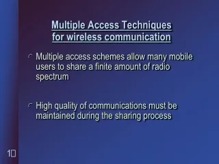
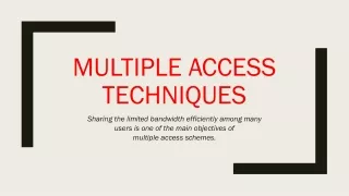
Multiple Access Techniques. Outline . FDMA TDMA CDMA Spread Spectrum. Multiple Access Techniques. Multiple users want to access the common BS or AP simultaneously If two or more user signals arrive at the BS at the same time, there will be interferences, unless the signals are orthogonal

E N D
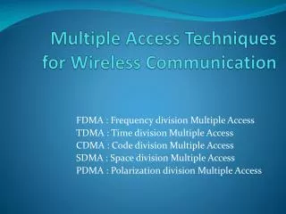
Outline • FDMA • TDMACDMA • Spread Spectrum
Multiple Access Techniques • Multiple users want to access the common BS or AP simultaneously • If two or more user signals arrive at the BS at the same time, there will be interferences, unless the signals are orthogonal • How can we achieve the orthogonality?
FDMA • The total bandwidth is divided into nonoverlapping frequency bands (channels) • Each user occupies a channel for the duration of the connection • waste of resources • Narrowband transmission • Forward and reverse links use FDD
TDMA • Time is partitioned into frames • Each frame consists of Nslot data slots plus a header and a trailer • Each slot is for transmission of one information unit • A user continues to use the same slot in every frame during call connection • waste of resources • TDMA systems require strict time synchronization.
TDMA • W-TDMA: Each user occupies the total frequency bandwidth during its slots • N-TDMA: The total frequency spectrum is divided into frequency subbands (channels); within each frequency channel, TDMA is used. −→Both time and frequency are partitioned.
Code Division Multiple Access (CDMA) • used in several wireless broadcast channels (cellular, satellite, etc) standards • unique “code” assigned to each user; i.e., code set partitioning • all users share same frequency, but each user has own “chipping” sequence (i.e., code) to encode data • encoded signal = (original data) X (chipping sequence) • decoding: inner-product of encoded signal and chipping sequence • allows multiple users to “coexist” and transmit simultaneously with minimal interference (if codes are “orthogonal”)
Code-Division Multiple Access (CDMA) • Basic Principles of CDMA • D = rate of data signal • Break each bit into kchips • Chips are a user-specific fixed pattern • Chip data rate of new channel = kD
d0 = 1 1 1 1 1 1 1 d1 = -1 1 1 1 1 1 1 1 1 1 1 1 1 1 1 1 1 1 1 1 1 1 1 1 1 1 1 - - - - - - - - - - - - - - - - - - - - - - - - - - - - - - - - 1 1 1 1 1 1 1 1 1 1 1 1 1 1 1 1 1 1 1 1 1 1 1 1 1 1 1 1 1 1 1 1 M Di = SZi,m.cm m=1 M d0 = 1 d1 = -1 CDMA Encode/Decode channel output Zi,m Zi,m= di.cm data bits sender slot 0 channel output slot 1 channel output code slot 1 slot 0 received input slot 0 channel output slot 1 channel output code receiver slot 1 slot 0
CDMA Example • If k=6 and code is a sequence of 1s and -1s • For a ‘1’ bit, A sends code as chip pattern • <c1, c2, c3, c4, c5, c6> • For a ‘0’ bit, A sends complement of code • <-c1, -c2, -c3, -c4, -c5, -c6> • Receiver knows sender’s code and performs electronic decode function • <d1, d2, d3, d4, d5, d6> = received chip pattern • <c1, c2, c3, c4, c5, c6> = sender’s code
CDMA Example • User A code = <1, –1, –1, 1, –1, 1> • To send a 1 bit = <1, –1, –1, 1, –1, 1> • To send a 0 bit = <–1, 1, 1, –1, 1, –1> • User B code = <1, 1, –1, – 1, 1, 1> • To send a 1 bit = <1, 1, –1, –1, 1, 1> • Receiver receiving with A’s code • (A’s code) x (received chip pattern) • User A ‘1’ bit: 6 -> 1 • User A ‘0’ bit: -6 -> 0 • User B ‘1’ bit: 0 -> unwanted signal ignored
Definitions • Correlation • The concept of determining how much similarity one set of data has with another • Range between –1 and 1 • 1 The second sequence matches the first sequence • 0 There is no relation at all between the two sequences • -1 The two sequences are mirror images • Cross correlation • The comparison between two sequences from different sources rather than a shifted copy of a sequence with itself
Advantages of Cross Correlation • The cross correlation between an m-sequence and noise is low • This property is useful to the receiver in filtering out noise • The cross correlation between two different m-sequences is low • This property is useful for CDMA applications • Enables a receiver to discriminate among spread spectrum signals generated by different m-sequences
Orthogonal Codes • Orthogonal codes • All pairwise cross correlations are zero • Fixed- and variable-length codes used in CDMA systems • For CDMA application, each mobile user uses one sequence in the set as a spreading code • Provides zero cross correlation among all users • Types • Welsh codes • Variable-Length Orthogonal codes
Walsh Codes • Set of Walsh codes of length n consists of the n rows of an n ´ n Walsh matrix: • W1 = (0) • n = dimension of the matrix • Every row is orthogonal to every other row and to the logical not of every other row • Requires tight synchronization • Cross correlation between different shifts of Walsh sequences is not zero
Spread Spectrum • important encoding method for wireless communications • analog & digital data with analog signal • spreads data over wide bandwidth • makes jamming and interception harder • two approaches, both in use: • Frequency Hopping • Direct Sequence
Spread Spectrum Advantages • immunity from noise and multipath distortion • can hide / encrypt signals • several users can share same higher bandwidth with little interference • CDM/CDMA Mobile telephones
Pseudorandom Numbers • generated by a deterministic algorithm • not actually random • but if algorithm good, results pass reasonable tests of randomness • starting from an initial seed • need to know algorithm and seed to predict sequence • hence only receiver can decode signal
Frequency Hopping Spread Spectrum (FHSS) • signal is broadcast over seemingly random series of frequencies • receiver hops between frequencies in sync with transmitter • eavesdroppers hear unintelligible blips • jamming on one frequency affects only a few bits
Slow and Fast FHSS • commonly use multiple FSK (MFSK) • have frequency shifted every Tc seconds • duration of signal element is Ts seconds • Slow FHSS has Tc Ts • Fast FHSS has Tc < Ts • FHSS quite resistant to noise or jamming • with fast FHSS giving better performance
Direct Sequence Spread Spectrum (DSSS) • each bit is represented by multiple bits using a spreading code • this spreads signal across a wider frequency band • has performance similar to FHSS