Download
1 / 30
550 likes | 1.95k Vues
PRESENTATION ON SYNCHRONOUS MACHINE MODEL. TANDIN JAMTSHO STUDENT #3226091. This presentation shall cover the following topics. Introduction Mathematical model Circuit based model used for both steady state and transient analysis Differential equation model Conclusion

E N D
PRESENTATION ON SYNCHRONOUS MACHINE MODEL TANDIN JAMTSHO STUDENT #3226091
This presentation shall cover the following topics • Introduction • Mathematical model • Circuit based model used for both steady state and transient analysis • Differential equation model • Conclusion • Discussion at the end of presentation
The main component of power system are Generator Transmission Line Step up Transformer Step down Transformer Load
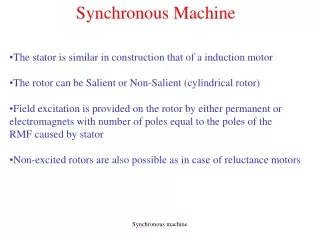
Principle of synchronous machine • Based on the principle of Faraday’s law of electromagnetic induction • Generally the armature winding are located on the stator and field winding on the rotor • The field winding is excited by a direct current
What is mean by synchronous machine ? • A machine that operates at constant speed and frequency with respect to time is called the synchronous machine. • N=120f/P • N=speed of the machine in rev/min • F=frequency in Hz • P=number of poles
Assumptions made are: • The stator windings are sinusoidally distributed electrically • The effect of the stator slots on the variation of any rotor inductances with rotor angle is neglected • Saturation effect neglected.
Mathematical model • Source of the diagram: • Mohamed E. El-Hawary, Electric Power Systems Design and Analysis
InductanceThe self inductance of any stator winding phases are given by The mutual inductance between any two stator phases are given by
Elimination of old variable ia ,ib,ic,by introducing a new variable io • Now I o=1/3(ia+ib+ic )
Under steady state operation, flux linkage in per unit along d and q axis and the voltage relation can be written as
On open circuit condition id=iq=0 • ed=0 and eq=xadifd • Voltage in the q-axis is due to excitation in the d-axis, lets denote it by E • E= xadifd • ed=xqiq-rid • eq=E-xdid-riq • e=ed+jeq • i=id+jiq • Eq=E-(xd-xq)id • eq=Eq-xdid-riq • eq=jEq-(r+jxq)I • J Eq=e+(r+jxq)i
Steady state Vector diagram F q-axis E D O A B C d-axis
OA=e • OD=current, i • AC=ir drop • CD=jxq • OD=e+(r+jxq)i • DE=j(xd-xq)id • OE=jE=jEq+j(xd-xq)id • If xd=xq, the triangle DEF will vanish for round rotor machine.
Determination of xd, xq and xo • From slip test • Xd=Max. voltage/Min. current • Xq=Min.voltage/Max current • Xd=open ckt. Voltage/Isc • By applying positive sequence current to the armature and measure the voltage for obtaining Xd and xq. • Xo is measured by connecting the three phase winding in series and passing single phase current • Xd will be within the range of 0.6 to 2.2 • Xq will be within the range of 0.4 to 1.4 • X0 will be within the range of 0.01 to 0.25 per unit for all the cases.
I ө Xs + +++ V 0 E δ - - Circuit based models for round rotor and salient pole synchronous machine are • Reactance of air gap flux is represented xo and the leakage flux reactance is represented by xl • Xs= xo+xl
D-axis equivalent circuit i1d id ifd
Q-axis equivalent circuit iq i1q
Transient circuit based model • D-axis equivalent circuit for the sub-transient period
Sub-transient and transient reactance • The idea of transient for a very short period is called Sub-transient, the sub-transient direct and quadrature axis are defined as • Xd’’=∆ d/∆id • Xq’’=∆ q/∆iq • Xd’’=Ll+ (1/(1/Lad+1/Lfd+1/L1d+---)) • Xq’’=Ll+ (1/(1/Laq+1/L1q+---)) • The transient which last for some time around 30 cycles is termed as transient, the transient reactance of direct and quadrature axis are given by • Xd’=Ll+ (1/(1/Lad+1/Lfd)) • Xq’=Ll+ (1/(1/Laq)) • X2=( Xd’’+ Xq’’)/2
Time constants • T’do=Xffd/rfd ( direct axis transient open circuit time constant, 2 to 11 seconds) • T’d=X’d*T’’do/Xd (direct axis transient short circuit time constant • T’’d=X’’d*T’’do/X’d (direct axis sub-transient time constant • T’’do =(x11d-x2f1d/xffd)/r1d (direct axis sub-transient open circuit time constant) • T’’qo=x11q/r1q • T’’q=x’’q*T’’qo/xq • Ta=x2/r (armature short circuit time constant)
Swing equation of synchronous machine • We know that per unit mechanical acceleration equation • p2Θ=(Tm-Te)/H’ • P=d/dt, Θ angle in electrical radians between d-axis and the centre of phase a axis. • H’=inertia constant of machine in per unit (KW-rad/kVA) • Tm=mechanical torque input in per unit • Te =electromagnetic torque developed in per unit • Since Θ is continuously changing with time, it is convenient to measure the angular position w.r.t synchronously rotating reference axis
Swing equation of synchronous machine • Θ=t+δ • the reference axis and the quadrature axis • The equation can be written as δ =angle between • p2 δ =(Tm-Te)/H’ • By expressing angle in degrees and time in seconds it becomes • p2 δ =180fb(Tm-Te)/H’ • Since p.u electrical torque =p.u air gap power developed • p2 δ =180fb(Pm-Pe)/H’
Swing equation of synchronous machine • In literature the quantities involved are expressed in their natural units without the use of per unit notation • p2 δ =(Pm-Pe)/M • M=GH/180fb, G is the rating of the machine in kVA, • H in kW-sec/kVA , Pm and Pe in kW
Conclusion • One can get the idea of basic machine parameters associated with synchronous machine for building models. • After understanding the machine parameters the models used in MATLAB are built. • This can help in choosing the right model for analysing the performance of the synchronous machine. • It will be very useful for those working in power stations.
Reference • Mulukutla S.Sarma, Synchronous Machine (Their Theory, Stability and Excitation Systems). • Charles Concordia, Shycnronous Machines Theory and Performance. • Mohamed E. El-Hawary, Electric Power Systems Design and Analysis • Yao-Nan Yu, Electric Power System Dynamics.