Download
1 / 38
880 likes | 1.62k Vues
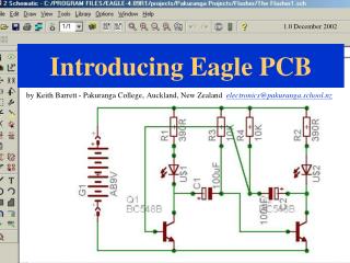
PCB Design (with EAGLE tutorial). TA: Robert Likamwa ELEC 424, Fall 2010. Printed Circuit Boards. What are they? How can I make one? 424 Project description Eagle Tutorial. http:// www.electronicmanufacturers.co.za /. What is a Printed Circuit Board?.

E N D
PCB Design (with EAGLE tutorial) TA: Robert Likamwa ELEC 424, Fall 2010
Printed Circuit Boards • What are they? • How can I make one? • 424 Project description • Eagle Tutorial http://www.electronicmanufacturers.co.za/
What is a Printed Circuit Board? • “A printed circuit board, or PCB, is used to mechanically support and electrically connect electronic components using conductive pathways, tracks or signal traces.” (Wikipedia)
How does it work? • Drilling (vias and holes) • Patterning (etching) • Subtractive process to remove copper cover from a preimpregnated substrate • Silk-screen printing of etch-resistant inks • Lamination • Multilayer PCBs • Coating (Solder and Solder mask /resist) • Printing text and symbols www.sunstone.com
Why do I need to know PCB Design? • Create your own embedded devices. • More robust than breadboard. Won’t fall apart. • Can use surface mount chips • Light in weight and size • Production quality devices • Put it on your resume… Recession-proof skill!
Steps to Design a PCB • Figure out Functional Design • Identify components to be used • Design schematic • Design PCB Layout and Routing
Function Design Schematic Component library Form factor constraints Layout Routing PCB design tool Design rules Production PCBexpress.com Assembly Any local workshops
Function Design • What’s your device supposed to do? • What sensors do you need to achieve your tasks? • How is everything going to be powered? • Will it fit in the provided space?
Component Selection • Which Integrated Circuit chips can perform your task? • Do they play nicely with each other? • Are they available from the distributor?
Through-hole components • Transistors, Resistors, Capacitors • DIP (Dual In-Line Package) Packages http://www.wikipedia.org/
Two-terminal SMD Packages • Surface Mount Devices • Resistors, Capacitors, LEDs, etc. • Usually given in hundredths of an inch • Careful, they can be given in metric, also. • Some common form factors: • 0805 (means 0.08” x 0.05”) • 1206 • 1210 • 1806 http://www.digikey.com/
IC Form Factors • Surface Mount Device (SMD) Chip form factors: • Small Outline IC (SOIC) (variants - TSOP, SSOP, TSSOP) • Quad Flat Package/No-lead QFP, QFN • Ball Grid Array (BGA) http://www.digikey.com/
Decoupling (Bypass) Capacitors • Remove noise by shunting noise. • 22-100uF for board (electrolytic or tantalum) • 10nF for each IC (ceramic) • Put capacitors as close as possible to ICs. Electrolytic (polar) Ceramic (non-polar) Vdd A B http://wikipedia.org
Steps to Design a PCB • Figure out Functional Design • Identify components to be used • Design schematic • Design PCB Layout and Routing Use Eagle!
Function Design Schematic Component library Form factor constraints Layout Routing PCB design tool Design rules Production PCBexpress.com Assembly Any local workshops
Project Description • Build a PCB to control the QuadRotor Helicopter. • Figure out tilt of board, control motors to balance. • Use gyroscope and accelerometer sensors. • Control altitude • Use ultrasound rangefinder • Offer user-control of movement via bluetooth. • Use MSP430 as the CPU (the “brain”)
Schematic Project Considerations • Gyroscope MUST be connected to I2C pins on MSP430 • Accelerometers and Rangefinder MUST be connected to ADC pins on MSP430
Add parts Move Clone Delete Mirror Rotate Group objects (try right-clicking!)
Schematic Exercise! Part 1 • New Project • New Schematic • Save it inside the project folder. • Use library “ricemobile.lbr” (Library->Use) • Add Part MAX604 (MAX604) • Add Part MSP430 (F16X---PM64) • Add Part KXM52 Accelerometer (KXM52) • Add Ground, Add VCC (From Supply Library)
Schematic Exercise! Part 2 • Connect GND wires on MAX604. • Clone GND, connect it to GND. Connect VCC to IN. • Add Electrolytic Capacitors (1206) to IN and OUT. • Rotate by right-clicking while moving it • Make sure minus side of capacitor is pointed to GND • Value the Capacitors appropriately (10 uF).
Schematic Exercise! Part 3 • Draw lines to connect • OUT_Y, OUT_Z on KXM52 • A1, A2 on MSP430 • Connect “wirelessly” • Draw line sticking out of OUT_X. • Draw line sticking out of A0. • Name both lines ACC1_X. • Label both of them. • By the way, you’re not finished here. There are resistors and capacitors that need to be placed around the KXM52. Always check the datasheets!
PCB Layout Considerations • Positions of the following need to be EXACT: • 4 mounting holes (1.75” square pattern) • Accelerometer (1.5”, 1.5”) • MSP430 (1.5”, 1.0”) (For accelerometer and MSP430, we’re sending in a stencil for PCB Assembly) • Board size needs to be 3”x3”
Layout Exercise! 1: Resize Board • Use “Move” tool • Type in (4.0 2.0) • This will select the rightmost border as if you clicked exactly there. • Type in (3.0 2.0) • This will move the cursor to that position, resizing the board to exactly 3”x3” • Then move all of your components in.
Poke holes in the right places • 1.75” apart in a square pattern on a 3” x 3” board 3” – 1.75” = 1.25” extra 1.25”/2 = 0.625” clearance 0.625”+1.75” = 2.375” (0.625, 0.625) (0.625, 2.375) (2.375, 0.625) (2.375, 2.375)
Layout Exercise! 2: Precision Layout • Draw 4 holes. • Use hole tool. Type: drillsize (xy) • 0.193 (0.625 0.625) • 0.193 (0.625 2.375) • 0.193 (2.375 0.625) • 0.193 (2.375 2.375) • Move KXM52 to its place (1.5 1.5) • Move MSP430 to its place (0.5 1.5)
Layout Exercise! 3: MAX604 on bottom • Put MAX604 and its capacitors on bottom by using Mirror tool. • Yellow lines are “Airwire” lines • Use Route Manually tool to turn Airwires into traces • Turn off Grid (View->Grid, Finest Grid) • Or just change grid spacing to what you want it to be. • Change line width as necessary at top of screen
Layout Exercise! 4: Connect • From KXM52, connect pin 6 to MSP430. • From KXM52, connect pin 9 to MSP430. • From KXM52, connect pin 7 to MSP430. • Go from top to bottom by selecting “Bottom” at the top-left of the screen. This will create a via. • Try to make your bottom traces as short as possible.
Layout Exercise! 5: Create GND Plane • Use Polygon tool to draw a GND Plane. (Make sure not to draw the plane beneath your bluetooth antenna) • Use the name tool to make it GND. • “Ratsnest” to see the result • Create GND vias near GND pins on KXM52 and MSP430. • Place Vias, then “Name” them GND. • Route the vias to the chips.
Create your own part • Some parts don’t have an Eagle footprint associated with them. • Let’s create our own gyroscope part.
Part Creation Tutorial 1 • Go to Control Panel (Window->Control Panel) • File->New Library • Save library as 424parts.lbr • Library->Symbol • Call it GYRO-BREAKOUT • Use “Draw a Pin” to add pins. Change names • SCL, SDA, CLK, INT, GND, VLOGIC, VDD
Part Creation Tutorial 2 • Library->Package • Call it GYRO-BREAKOUT • Draw 7 Pads in a row. Space them by 0.100” • Drill size set to ~0.043307 • Rename the pads if you want to. • Draw a box around the 7 pads with “Draw Lines”
Part Creation 3 • Library->Symbol • Call it GYRO-BREAKOUT • Add a Part • Select GYRO-Breakout, lay it down • Click “New” button (on right side) • Select GYRO-Breakout • Click Connect • Assign pins to the symbol to pins on the device appropriately. • SCL, SDA, CLK, INT, GND, VLOGIC, VDD • Now if you want to use the part, all you have to do in a schematic is Use Library & Add Part.
Where to go from here: • Design Rule Checking • Find the Sunstone design rules online. • http://www.sunstone.com/pcb-resources/downloads.aspx • DFM Add-ons • Follow its provided instructions to check your design rules. • Create Gerber Files • Gerber: standard file format for patterns on PCB – used by most fabrication houses • Send Gerber Files to PCBExpress
Create Gerber Files • Download http://www.pcbexpress.com/downloads/Sunstone-EagleCam.zip • Use instructions at: http://www.pcbexpress.com/downloads/EAGLE%20Convert-Sunstone%20Protos.pdf • Open your board • Click on ULP then select “drillcfg.ulp” • Click on CAM then select “excellon.cam” • Click on CAM then select “xLPlus-Sunstone.cam" • x = number of layers • Note which layers you want for each file • Dimension layer (20) should be selected in all files • Important: always check your Gerber files afterwards • Free viewer: http://www.pentalogix.com/download/viewmate9_825.exe
Send files to PCBExpress • Outline: .oln • Drill hole locations/size: .drd/.drl • Copper layers: .l1, .l2, .l3, .l4 • Top/bottom solder mask: .smt/.smb • Top/bottom silkscreen: .slk/.slb • Top/bottom soldering stencils: .tps/.bps (May be different files for you)
And that’s the tutorial! • Now you know how to Layout a PCB. The rest comes from experience! • Just remember to always read the datasheets for all components. • Further project specifications will be provided.