Download
1 / 24
250 likes | 417 Vues
Chapter 12 Processes. CHAPTER OPENER FIGURE Die casting. Image courtesy of Thomas Publishing, New York. A process = method of shaping, joining or finishing a material. There are hundreds of processes. Which one to use for our application?. Depends on materials, its size, shape,

E N D
Chapter 12 Processes
CHAPTER OPENER FIGURE Die casting. Image courtesy of Thomas Publishing, New York.
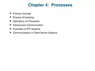
A process = method of shaping, joining or finishing a material There are hundreds of processes. Which one to use for our application? Depends on materials, its size, shape, required precision, and how many to be made. i.e. design requirements We need to first classify the processes to be able to select Processing has two functions shaping and microstructure FIGURE 13.1 Processing selection depends on material and shape. The “process attributes” are used as criteria for selection.
FIGURE 13.2 The classes of process. The first row contains the family of shaping processes; below lie the secondary processes of machining and heat treatment, followed by the families of joining and finishing (surface treatment) processes.
FIGURE 13.3 The taxonomy of the kingdom of process with part of the shaping family expanded. Each member is characterized by a set of attributes. Process selection involves matching these to the requirements of the design.
FIGURE 13.4 The taxonomy of the process kingdom again, with the families of joining and finishing partly expanded.
Poor surface finish Best surface finish Avoids turbulent flow and inclusion of oxides and gas FIGURE 13.5 Casting processes. In sand casting, liquid metal is poured into a split sand mold. In die casting, liquid is forced under pressure into a metal mold. In investment casting, a wax pattern is embedded in a refractory, melted out, and the cavity filled with metal. In pressure casting, a die is filled from below, giving control of atmosphere and of the flow of metal into the die.
Cheaper molds FIGURE 13.6 Molding processes. In injection molding, a granular polymer (or filled polymer) is heated, compressed, and sheared by a screw feeder, forcing it into the mold cavity. In blow molding, a tubular blank of hot polymer or glass is expanded by gas pressure against the inner wall of a split die. In polymer extrusion, shaped sections are formed by extrusion through a shaped die. In thermo-forming, a sheet of thermoplastic is heated and deformed into a female die by vacuum or gas pressure.
Can be hot, warm and cold FIGURE 13.7 Deformation processes. In forging, a slug of metal is shaped between two dies held in the jaws of a press. In rolling, a billet or bar is reduced in section by compressive deformation between the rolls. In extrusion, metal is forced to flow through a die aperture to give a continuous prismatic shape. All three processes can be hot (T > 0.85 Tm), warm (0.55 Tm < T < 0.85 Tm), or cold (T < 0.35 Tm). In spinning, a spinning disc of ductile metal is shaped over a wooden pattern by repeated sweeps of the smooth, rounded tool.
According to deformation temperature Adv. Of both worlds. Steel 650-700oC. Temp low avoid scaling, Hot working Cold working Warm working • Working of preheated material. • Advantages: • Low flow stresses (low forces and power requirements) • High ductility (large deformations, excess of 99% • can be done, complex part generate) • 3. Cast structure destroyed 75% reduction in area or height. Normally refers to working at r.t.. Usually follows hot working Adv. since no cooling problems and scales better surface finish and thinner walls possible`. Can control final properties of work piece through annealing/recrystallization. Disadv. R.t <0.5Tm high flow stresses high power requirements Hot Working can be carried out by Non-isothermal forming. Work piece higher temp. than dies. Variable cooling variable properties thermal fatigue of tooling Isothermal forming avoids above problems, but need very good die material and lubricants Controlled Hot Working -conducted non isothermally to impart desirable properties
OPEN-DIE FORGING Cogging, Drawing out
Impression Die and Closed Die Forging Impression die Forging CLOSED DIE Forging Material fills entire mold with no flash
EXTRUSION Direct vs. indirect extrusion
Initial area Deformed area Extrusion pressure Extrusion constant Extrusion ratio Extrusion speed Extrusion ratio Extrusion Temperature Discard
Die Geometry: Flat vs. conical die (surface quality) • Hydrostatic extrusion • no friction, long billets can be used. Cold extrusion of copper tubes Canning
FIGURE 13.8 Powder processing. In die-pressing and sintering the powder is compacted in a die, often with a binder, and the green compact is then fired to give a more or less dense product. In hot isostatic pressing, powder in a thin, shaped shell or preform is heated and compressed by an external gas pressure. In powder injection molding, powder and binder are forced into a die to give a green blank that is then fired. In slip casting, a water-based powder slurry is poured into a porous plaster mold that absorbs the water, leaving a powder shell that is subsequently fired.
FIGURE 13.9 Composite forming methods. In filament winding, fibers of glass, Kevlar, or carbon are wound onto a former and impregnated with a resin-hardener mix. In roll and spray lay-up, fiber reinforcement is laid up in a mold onto which the resin-hardener mix is rolled or sprayed. In vacuum-bag and pressure-bag molding, laid-up fiber reinforcement, impregnated with resin-hardener mix, is compressed and heated to cause polymerization. In pultrusion, fibers are fed through a resin bath into a heated die to form continuous prismatic sections.
FIGURE 13.10 Rapid prototyping. In deposition modeling and ballistic particle manufacture (BPM), a solid body is created by the layer-by-layer deposition of polymer droplets. In stereo-lithography (SLA), a solid shape is created layer by layer by laser-induced polymerization of a resin. In direct mold modeling, a sand mold is built up layer by layer by selective spraying of a binder from a scanning print-head. In laminated object manufacture (LOM), a solid body is created from layers of paper, cut by a scanning laser beam and bonded with a heat-sensitive polymer.
FIGURE 13.11 Machining operations. In turning and milling, the sharp, hardened tip of a tool cuts a chip from the work piece surface. In drawing, blanking, and stretching, sheet is shaped and cut to give flat and dished shapes. In electro-discharge machining, electric discharge between a graphite electrode and the work piece, submerged in a dielectric such as paraffin, erodes the work piece to the desired shape. In water-jet cutting, an abrasive entrained in a high-speed water jet erodes the material in its path.
FIGURE 13.12 Joining operations. In adhesive bonding, a film of adhesive is applied to one surface, which is then pressed onto the mating one. Fastening is achieved by bolting; riveting; stapling; push-through snap fastener; push-on snap fastener; or rod-to-sheet snap fastener. In metal fusion welding, metal is melted, and more is added from a filler rod to give a bond or coating. In thermoplastic polymer welding, heat is applied to the polymer components, which are simultaneously pressed together to form a bond.
FIGURE 13.13 Finishing processes to protect and enhance properties. In mechanical polishing, the roughness of a surface is reduced and its precision increase, by material removal using finely ground abrasives. In electroplating, metal is plated onto a conducting work piece by electro-deposition in a plating bath. In heat treatment, a surface layer of the work piece is hardened and made more corrosion resistant by the inward diffusion of carbon, nitrogen, phosphorous, or aluminum from a powder bed or molten bath. In anodizing, a surface oxide layer is built up on the work piece (which must be aluminum, magnesium, titanium, or zinc) by a potential gradient in an oxidizing bath.
FIGURE 13.14 Finishing processes to enhance appearance. In paint spraying, a pigment in an organic- or water-based solvent is sprayed onto the surface to be decorated. In polymer powder-coating a layer of thermoplastic is deposited on the surface by direct spraying in a gas flame, or by immersing the hot work piece in a bed of powder. In silk-screen printing, ink is wiped onto the surface through a screen onto which a blocking pattern has been deposited, allowing ink to pass in selected areas only. In pad-printing, an inked pattern is picked up on a rubber pad and applied to the surface, which can be curved or irregular.
FIGURE 13.15 The extent of the material bubbles on the property charts gives an idea of the degree to which properties can be manipulated by processing.