Download
1 / 37
370 likes | 481 Vues
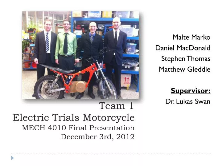
Malte Marko Daniel MacDonald Stephen Thomas Matthew Gleddie Supervisor: Dr. Lukas Swan. Team 1 Electric Trials Motorcycle MECH 4010 Final Presentation December 3rd, 2012 . Outline. Problem Definition Design Process Final Design Budget. S. Thomas, 2012. M. Gleddie , 2012.

E N D
Malte Marko Daniel MacDonald Stephen Thomas Matthew Gleddie Supervisor: Dr. Lukas Swan Team 1 Electric Trials MotorcycleMECH 4010 Final PresentationDecember 3rd, 2012
Outline Problem Definition Design Process Final Design Budget S. Thomas, 2012 M. Gleddie, 2012
What Is Trials Motorcycling? Technical High Torque Low Speed High Control Not a race! S. Manchester, 2012
Design Requirements Throttle Response Battery Leads New: Battery Management System! S. Manchester, 2012 Water Resistance Noise
Sound Testing M. Gleddie, 2012
Prototype 2 Sound Requirement 91 dB 25 % reduction in sound wave pressure 88 dB
Re-Orientation of Leads • Side View • Top View S. Thomas, 2012 Power and BMS Leads to Top of Pack Consolidate Wiring Plugs to Single, Central Point. S. Thomas, 2012 Messy, Prone to Damage
Battery Management System • Constantly check between cells for over-voltage (3.6V) • Manually turn on/off power supply • Shunt power resistors S. Thomas, 2012
Rejected ideas – BMS • On-Board BMS • Weight • No need for discharge balancing (Throttle Response) • Arduino Control W/ Relay Power Resistor • Emulates physical charging sequence • Complicated apparatus, high • likelihood of user error/malfunction • CCCV power supply shutoff problems Arduino, 2012
Battery Management System • Final Design: FET Circuit • Limits cell voltages to 3.6V • Dissipates excess current to heat sink • Selectable characteristics
Full FET Circuit 8 FET circuits in total Dissipate over-voltage power through back of FET to common heat sink (Al, finned, 10cm x 40cm)
BMS Plan B PreFab Unit Over-Designed, Expensive - Capable of measuring up to 108 cells connected in series based on configuration. - Performs intelligent cell balancing (passive). - Calculates state of charge (SOC). - Uses professional automotive-grade locking connectors. - Calculates discharge current limit (DCL) and charge current limit (CCL). - Can measure cell voltages between 0.5v and 5.0v. Orion BMS, 2012
Current Drive Train Problems • Motor and shaft mounts are separate • Bent shaft mount – misalignment • Open motor • 7:1 reduction • Noise! S. Thomas, 2012
Rejected Ideas Planetary Gear Reduction Flywheel and Clutch Flywheel Clutch One Stage Gear Reduction Hub Motor Goldenmotor.ca
Selected Motor HPM-5000b from goldenmotor.com 5kW 48 V 100 amp continuous 300 amp peak (30 seconds) Water resistant Aluminum case, SS shaft 4000 RPM on 48 volts Goldenmotor.ca
Primary Reduction - Belt Gates Mectrol 2012 Gates Mectrol 2012
Drive Train • Primary Reduction • Change ratio to 3:1 (from 1.8:1) • Secondary Reduction • Change ratio to 5:1 (from 7.1:1) • Use lighter 520 chain • Use stock parts
Drive Train Bracket Minimize loads Protect components Mount to frame • TBD • Stress calculations • Build prototype
Controller/Throttle Response Kelly KBL48201 (from department) 48 V 100 amp continuous 200 amp peak (1 minute) 260 amp boost (10 seconds) Sealed Torque control, speed control, or a mix S. Thomas, 2012
Goals for the winter term • December • Finalize FET circuit • Order Parts • Bracket stress analysis • January • Program controller • Assembly • February-April • Testing • Fix • Go play in the mud! M. Gleddie, 2012
Thank You! Michael Traves Jon MacDonald Angus MacPherson Albert Murphy Dr. Tim Little Sebastian Manchester 2011/2012 ETM Design Team Dr. Lukas Swan Dr. Julio Militzer
References Arduino Mega Photo – Slide 11 http://arduino.cc/en/Main/ArduinoBoardMega2560 Orion BMS – Slide 14 http://www.orionbms.com/products/orion-bms-standard/
Existing Prototype Recommendations from 2011/2012 team Belt on Primary Reduction Reduce Noise Waterproofing Protect Battery leads Smaller chain
Sound Testing Results From Fall 2012 Term Report
Battery Energy Storage System 48V System 64 Li-Ion Cells Nominal 3.3V each, 3.6V full charge Nominal 528 Wh of energy storage
FET Characteristics FET Specs: V1 < V2 < 3.6V Capable of dissipating 20A at 3.6V (72W) To be finalized based on VDC