Download
1 / 24
240 likes | 252 Vues
This article introduces the concept of OSPF Topology-Transparent Zone (TTZ) and discusses how it can address scalability issues and improve network operations. It provides an overview of TTZ, its benefits compared to traditional OSPF areas, and explains how to configure OSPF TTZ. The article also highlights the advantages of TTZ in terms of scalability, end-to-end services, and higher availability.

E N D
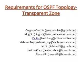
OSPF Topology-Transparent Zone Huaimo Chen, Renwei Li (Huawei) Gregory Cauchie (France Telecom) Ning So (Verizon)
Contents • Introduction • What is TTZ? • Why TTZ? • How TTZ? Page 2
Introduction • What happens if a network is bigger and bigger? • Scalability Issue, Slower convergence, etc. • Problems in Current Solution Using Area • Limitation on Scalability: at most two levels of hierarchies • Very complex to provide end to end services • Service interruptions when splitting ASes/Areas since Network Architecture is changed significantly • Harder to operate & maintain network with more/multiple ASes & areas • Not easy for applications/software to be aware of/drive/control networks with more/multiple ASes and areas in near future • Harder for inter-cloud networking with more/multiple ASes and areas • TTZ may resolve these issues
Contents • Introduction • What is TTZ? • Definition of TTZ • Configuring OSPF TTZ • TTZ vs Area • Why TTZ? • How TTZ? Page 4
Definition of TTZ • A group of routers connected by links with TTZ ID • which is virtualized as • a group of TTZ edge routers fully connected or • a single router • of which routers outside TTZ are NOT aware • through which LSAs outside are distributed
T3 T3 T2 T1 T1 T6 T5 T7 T9 T4 T4 T8 T10 T10 TTZ As a Group of Edge Routers Connected (Animated) R6 R1 R2 R7 R8 R9 R3 R10 R4 R5 R11 • A group of routers connected by links with attribute TTZ ID. • Routers outside of TTZ are NOT aware of TTZ, just see the edge routers of TTZ, which are connected. • Links, routers inside TTZ are NOT advertised to routers outside of TTZ.
TTZ as a Single Router (Animated) T3 T2 T1 T6 T5 T7 T9 T4 T8 T10 TTZ RT R6 R1 R2 R7 R8 R9 R3 R10 R4 R5 R11 Routers outside of TTZ are NOT aware of TTZ, Just see TTZ as a Single Router.
Configuring OSPF TTZ R2 OSPF R3 OSPF Eth1/0 Eth3/0 Eth3/0 Eth1/0 OSPF OSPF OSPF P2 P1 OSPF OSPF Eth4/0 Eth0/0 Eth0/0 Eth2/0 Eth2/0 Eth4/0 OSPF OSPF Eth2/0 Eth2/0 Eth4/0 OSPF Eth1/0 Eth4/0 Eth1/0 Eth1/0 Eth3/0 Eth1/0 Eth3/0 R4 San Francisco R1 TTZ Configurations on router R2: router ospf 1 Interface ethernet 1/0 ip address 10.10.120.1/24 Interface ethernet 2/0 ip address 192.168.20.1/24 ttz 192.168.100.100 Interface ethernet 3/0 ip address 192.168.30.1/24 ttz 192.168.100.100 Interface ethernet 4/0 ip address 192.168.40.1/24 ttz 192.168.100.100 No configuration changes on router outside TTZ Configurations on router P1: router ip ospf 1 Interface ethernet 0/0 ip address 10.10.120.1/24 Interface ethernet 1/0 ip address 10.10.220.1/24 Configure TTZ ID on an interface in TTZ
TTZ vs Area TTZ has functions of Area & improves on Area OSPF TTZ: • Virtualize TTZ as a router or a group of routers • Can see through a TTZ • 2+ levels of hierarchies • Easy to set up TE LSP crossing TTZs • Minor network architecture changes when TTZ is used in a network OSPF Area: • 2 levels of hierarchies • Complex to set up TE LSP crossing areas • Significant network architecture changes when multiple areas are introduced to a network
Contents • Introduction • What is TTZ? • Why TTZ? • Improves Scalability 1 Order of Magnitude • E2E Services Can Be Set Up Easily • Higher Availability • How TTZ? Page 10
Improves Scalability:1 Order of Magnitude (Animated) T3 T3 T3 T3 T3 T3 T3 T3 T3 T3 T3 T2 T1 T6 T5 T7 T9 T4 T8 T10 T10 T10 T10 T10 T10 T10 T10 T10 T10 T10 TTZ 1 Area 4 One more hierarchies Area 1 Area 0 TTZ TTZ Area 0 Area 3 TTZ TTZ Area 2 TTZ RT1 R5 R1 R6 R7 R8 R2 R9 R3 R4 R10
E2E TE LSP can be set up easily (Animated) T3 T2 T3 T1 T6 T1 T5 T7 T9 T4 T8 T4 T10 TTZ T10 R5 R1 R6 R7 Destination R8 R2 R9 R3 Source R4 R10 Find path from R3 to R6 in a normal way Find path from T4 to T10 in a normal way Path for LSP is computed easily in a normal way LSP can be set up along the path computed
R2 R3 Eth3/0 Eth3/0 Eth4/0 Eth2/0 Eth2/0 Eth4/0 Eth2/0 Eth2/0 Eth4/0 Eth4/0 Eth3/0 Eth3/0 R4 San Francisco R1 TTZ Higher Availability Eth1/0 Eth1/0 P2 • The routing tables on P1 and P2 are not re-calculated. • There will be no downloading from RIB to FIB. • When considering more complex POPs as TTZs, a failure or crash of a router inside a POP will not affect anything outside of POP. And thus availability is higher. P1 Eth0/0 Eth0/0 Eth1/0 Eth1/0 Eth1/0 Eth1/0 • Suppose the Link R2-R3 Is Broken • Routers outside not aware of this
Issues in a Bigger Network: Split to Areas(animated) Area 4 Area 1 R5 T3 R5 T3 T2 T2 T1 R1 R6 T1 R1 R6 T6 T6 T5 T7 T5 T7 R7 R7 T9 T9 R2 R2 T4 R8 T4 T8 R8 T8 R3 R3 T10 Area 0 T10 R9 R9 R4 R4 Area 3 R10 R10 Area 0 Area 2 1. Significant changes on Network Architecture and configuration when split area, service may be interrupted
TTZ Avoids Splitting to Areas(Animated) T3 T3 T3 T3 T3 T3 T3 T2 T3 T3 T3 T1 T6 T T1 T T5 T7 T9 T4 T8 T4 T10 T10 T10 T10 T10 T10 T10 TTZ 1 T10 T Area 0 1. No need to split area (one area) 2. Smaller changes on Network Architecture and configuration, network is more stable
Contents • Introduction • What is TTZ? • Why TTZ? • How TTZ? • OSPF Data Change — I bit • LSA Generation and Flooding • Adjacency Establishment • Routing Table Computation Page 16
OSPF Data Change — I bit 1 bit to identify if a link is in TTZ Router LSA 0 1 2 7 LS Age Options LS Type = 1 Link Type Link State ID Header Advertising Router LS Sequence Number LS Checksum Length Flags Number of Links 0 1 2 7 I bit = 1 if link in TTZ Router Link Link Type I . . . . . . I bit = 1 if link in TTZ Router Link I = 1: Link is in TTZ I = 0: Link is not in TTZ Meaning of “Link Type” of 7 bits is the same as that of “Link Type” of 8 bits. Page 17
LSA Generation and Flooding • Every router in TTZ generates a router LSA containing all the router links, each of which has I bit set to 1 if it is configured with TTZ ID. This LSA is flooded inside TTZ. • TTZ virtualized as • A group of routers connected: TTZ edge router constructs a second router LSA and sends it to all its neighbors. This LSA comprises two groups of links. • The router links connecting the routers outside of the TTZ from this TTZ edge router. These router links are normal router links. There is a router link for every adjacency between this TTZ edge router and a router outside of the TTZ. • The "virtual" router links. For each of the other TTZ edge routers, there is a "virtual" router link to it from this TTZ edge router. The cost of the router link from this TTZ router to one of the other TTZ edge routers is the cost of the shortest path from this TTZ edge router to it. • A single router: DR of TTZ constructs a second router LSA and sends it to all its neighbors. This LSA comprises links between a TTZ edge router and a router outside of TTZ. Page 18
Router LSA Generated by T1/T5 to inside TTZ T3 T2 T1 T6 T5 T7 T9 T4 T8 T10 TTZ R6 R1 R2 R7 R8 R9 R3 R10 R4 R11 R5 LS Age Options LS Type = 1 LS Age Options LS Type = 1 Header Header Link State ID (T1) Link State ID (T5) Advertising Router (T1) Advertising Router (T5) LS Sequence Number LS Sequence Number Length Length LS Checksum LS Checksum Flags Number of Links Flags Number of Links I=0 for Normal Link I=1 for TTZ Link Router Link: T1 to R2 Router Link: T5 to T1 I=1 for TTZ link I=1 for TTZ link Router Link: T1 to T2 Router Link: T5 to T4 I=1 for TTZ link I=1 for TTZ link Router Link: T1 to T4 Router Link: T5 to T6 I=1 for TTZ link I=1 for TTZ link Router Link: T1 to T5 Router Link: T5 to T9
Router LSA by T1 to outside TTZ as a Group of Nodes Connected T3 T1 T4 T10 R6 R1 R2 R7 R8 R9 R3 R10 R4 R11 R5 LS Age Options LS Type = 1 Link State ID (T1) Header Advertising Router (T1) LS Sequence Number LS Checksum Length Flags Number of Links Normal Link Router Link: T1 to R2 Normal Link (“virtual”) Router Link: T1 to T3 Router Link: T1 to T4 Normal Link (“virtual”) Router Link: T1 to T10 Page 20
Router LSA Generated to outside TTZ as a Single Node RT R6 R1 R2 R7 R8 R9 R3 R10 R4 R11 R5 LS Age Options LS Type = 1 Link State ID (RT) Header Advertising Router (RT) LS Sequence Number LS Checksum Length Flags Number of Links Normal Link Router Link: RT to R2 Normal Link Router Link: RT to R3 . . . Router Link: RT to R10 Normal Link Router Link: RT to R11 Page 21
Adjacency Establishment • Between TTZ edge and non TTZ router, TTZ edge • for TTZ as a group of routers connected • sends non TTZ router hellos in a normal way, and • sends non TTZ router all the LSAs except for the LSAs belong to TTZ during LSDB synchronization. • for TTZ as a single router RT • sends non TTZ router hellos in a normal way but with RT ID, and • sends non TTZ router all the LSAs except for the LSAs belong to TTZ during LSDB synchronization. • After adjacency is established, when TTZ edge router floods a LSA, • it only floods the LSA that does not belong to TTZ to the non TTZ router through the adjacency between the TTZ edge router and the non TTZ router. Page 22
Routing Table Computation T3 T3 T3 T3 T3 T3 T3 T2 T3 T3 T1 T6 T T T5 T7 T9 T4 T8 T10 T10 T10 T10 T10 T10 T10 TTZ 1 T Router in TTZ builds SPF tree using topology it sees Area 0 Page 23
Next Step • Welcome comments