Download
1 / 21
210 likes | 313 Vues
Overview on Compton Polarimetry. General Issues O spin motion & alignment tolerances O beam-beam effects & upstream vs. Downstream Compton Polarimetry Basics O beam parameters & Compton detection methods O kinematics, cross sections & asymmetries O laser choices and parameters

E N D
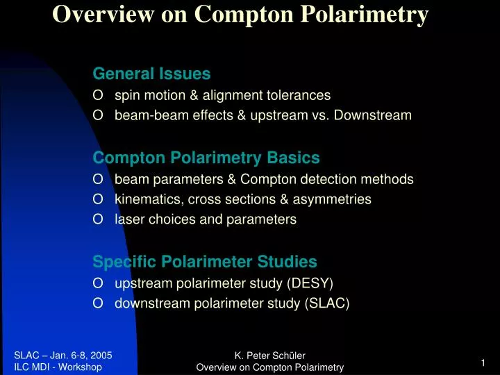
Overview on Compton Polarimetry General Issues O spin motion & alignment tolerances O beam-beam effects & upstream vs. Downstream Compton Polarimetry Basics O beam parameters & Compton detection methods O kinematics, cross sections & asymmetries O laser choices and parameters Specific Polarimeter Studies O upstream polarimeter study (DESY) O downstream polarimeter study (SLAC) K. Peter Schüler Overview on Compton Polarimetry
Spin Motion • Spin vector must be vertical in the damping ring • Spin Rotator in the transfer line to the linac: manipulates spin direction for any desired orientation at the experiment must compensate all technical spin rotation effects along the machine requires fast polarimeter at the high-energy end for efficient tune-up • Spin orientation is extremely sensitive to orbit deflections, • at 250 GeV: spin = 567 orbit K. Peter Schüler Overview on Compton Polarimetry
Spin motion along the accelerator (e.g. for TESLA TDR topology) K. Peter Schüler Overview on Compton Polarimetry
Alignment Tolerances • i.e. beam orbit directions at the polarimeter & e+e- detector must be extremely well aligned to each other • very tight, but not impossible • will require high-precision BPM‘s & surveying techniques • applies to any kind of polarimetry method & location K. Peter Schüler Overview on Compton Polarimetry
Beam-Beam Effects I: depolarization estimates for TESLA angular spread of disrupted beam leads to corresponding spread of spin vector distribution • estimated depolarization* of disrupted beam: 1 % (extracted beam) of beam at e+e- IP: 0.25% (lumi-weighted) * only Thomas-BMT spin rotations effects considered K. Peter Schüler Overview on Compton Polarimetry
Kathleen Thompson: SLAC-PUB-8761 (Jan. 2001) (see also Yokoya & Chen: SLAC-PUB-4692) NLC-500: outgoing e- depolarization: BMT ST TOTAL BMT ST TOTAL (analytic results) (simulation results) NLC-A 0.6% 0.4% 1.1% 0.4% 0.5% 0.9% NLC-B 0.8% 0.4% 1.1% 0.5% 0.4% 0.9% NLC-C 0.9% 0.3% 1.1% 0.5% 0.3% 0.9% NLC-500: luminosity-weighted e- beam depolarization: BMT ST TOTAL BMT ST TOTAL (analytic results) (simulation results) NLC-A 0.2% 0.1% 0.3% 0.1% 0.1% 0.2% NLC-B 0.2% 0.1% 0.3% 0.1% 0.1% 0.2% NLC-C 0.2% 0.1% 0.3% 0.1% 0.1% 0.2% Beam-Beam Effects II: depolarization studies for NLC P (downstream) 4 x P (lumi-weighted) upstream value is much closer to lumi-weighted polarization! K. Peter Schüler Overview on Compton Polarimetry
beam parameters & Compton detection methods • typical e+/e- beam parametersHERA SLC ILC • beam energies (GeV): 27.5 45.6 45.6; 250; 400; 500 • bunch population 4 · 10104 · 10102 · 1010 • no. of bunches per pulse 2 820 • no.ofpulses per sec 5 • no. ofbunches per sec 10.4 · 10 6 120 14 100 • bunch separation 96 ns 8.3 ms 337 ns • average beam current~ 50 mA~ 0.8 A ~ 45 A • Compton detection methods HERA HERA HERA SLD ILC • TPOL LPOL Cavity • long/trans || || || || • e vs. detection e () e () • single event counting yes no yes no (no) • multi event detection no yes yes yes yes • laser pulse rate (Hz) cw 100 cw 17 5 (*) • 14 100 (**) • * downstream / ** upstream polarimeter proposals K. Peter Schüler Overview on Compton Polarimetry
Compton Kinematics K. Peter Schüler Overview on Compton Polarimetry
Compton Polarimetry cross sections, spin asymmetry, scattering angles - 1 < P < + 1 - 1 < < + 1 K. Peter Schüler Overview on Compton Polarimetry
standard detection method: scattered electron detection with suitable magnetic spectrometer Eo = 250 GeV o = 2.33 eV (green) Eo = 400 GeV o = 1.165 eV (IR) Eo = 45.6 GeV o = 4.66 eV (UV) may need to adjust wavelength of laser to obtain acceptable coverage of Compton edge region for all beam energies K. Peter Schüler Overview on Compton Polarimetry
Photon Detection Option(with suitable calorimeter) analyzing power = asymmetry of energy-weighted cross section integrals May be attractive for Giga-Z (Eo = 45.6 GeV), to avoid need for UV-lasers K. Peter Schüler Overview on Compton Polarimetry
Luminosity for pulsed lasers fb = bunch crossings per sec Ne, N = no. of e, per bunch g = geometry factor x , y = transverse laser beam size z = c t = laser pulse length o = laser crossing angle effectiveness of laser degrades with increasing pulse length & crossing angle K. Peter Schüler Overview on Compton Polarimetry
laser choices & parameters • Q-switched Nd:YAG laser • pro very high pulse energy (up to several 100 mJ), • robust commercial systems, relatively low cost • con very low rep-rate (~5 Hz), i.e. only a small sampling fraction (1/2820) • of all ILC bunches can be measured; • inefficient due to long pulse length (ns‘s) • 2.TESLA TTF rf-gun type Nd:YLF laser • pro pulse pattern matched to ILC bunch & pulse structure; • 100% of all ILC bunches will be measured; • high efficiency due to short pulse length (10 ps); • sufficient pulse energy (10-100 J) to achieve negligible stat. errors in 1 sec ! • con non-commercial system, ~ 400 k€ per laser • Pulsed Fabry-Perot Cavity (R&D project at Orsay) • pro aims for similar performance as (2) • con must operate complex laser system remotely in ILC tunnel (reliability!); • feasibility must still be demonstrated (note: HERA Fabry-Perot is not pulsed!) K. Peter Schüler Overview on Compton Polarimetry
Nd:YLF laser parameters I laser schematic of TTF injector gun: regen. multi-stage Nd:YLF ampl. (built by Max-Born-Inst.) operates at nominal pulse & bunch pattern of TESLA K. Peter Schüler Overview on Compton Polarimetry
Nd:YLF laser parameters II t = 8 ps Laser for TTF injector gun S. Schreiber et al. NIM A 445 (2000) 427 K. Peter Schüler Overview on Compton Polarimetry
Specific Polarimeter Studies A. upstream polarimeter study (DESY) For details: V. Gharibyan, N. Meyners, K.P. Schüler, www.desy.de/~lcnotes/notes.html LC-DET-2001-047 K. Peter Schüler Overview on Compton Polarimetry
Specific Polarimeter Studies B. downstream polarimeter study (SLAC) low-energy Compton electrons will be well-separated from disrupted beam (for 20 mrad linac crossing angle!) 4-magnet chicane with 2nd beam focus and laser crossing at center of chicane for details: M. Woods and K.C. Moffeit, SLAC-PUB-10669, Aug. 2004, and K.C. Moffeit, this workshop Laser: 532 nm, 100 mJ, 2 ns FWHM, 5 Hz, 100 m spot size, 11.5 mrad beam crossing angle K. Peter Schüler Overview on Compton Polarimetry
Upstream polarimeter study (DESY): assumes suitable magnetic bend (~ 1 mrad) with dog-leg or chicane geometry custom-built laser system (similar to existing facility at DESY) with pulse pattern matched to ILC bunch structure (14 100 per sec) very fast, robust facility, precision of P/P ~ 0.25% Downstream polarimeter study (SLAC): Assumes 20 mrad linac crossing angle with suitable magnetic chicane commercial laser system (similar to SLD polarimeter laser) which samples fraction of ILC bunches (5 per sec) Low-energy Compton electrons are well-separated from disrupted beam background, precision of P/P ~ 0.25% Summary K. Peter Schüler Overview on Compton Polarimetry
additional material: downstream (extractionline) studies for TESLA TESLA beam extraction scheme Laser Beam Topology place Compton electron detector at z = 65 m (behind MSEP magnet) laser beam crossing inside the big detector! K. Peter Schüler Overview on Compton Polarimetry
additional material: downstream (extractionline) studies for TESLA 250 GeV nominal beam energy, 40 000 disrupted beam events, simulated with „guinea pig“, distributions at e+e- IP extrapolated background (at IP & z = 65 m) for standard 20 mm x 20 mm collimator aperture K. Peter Schüler Overview on Compton Polarimetry
Compton el. detector at z = 65 m additional material: downstream (extractionline) studies for TESLA green laser (same type as for upstream polarimeter) Conclusion: large background from disrupted beam; downstream polarimetry is not possible for head-on linac configurations! K. Peter Schüler Overview on Compton Polarimetry