Download
1 / 7
80 likes | 107 Vues
Bionic Arm is the best revolution idea for amputees across the world. This is as close as we can get to our natural limb. This paper is about the study of the prosthetic arm used for amputees and gives an overview of upper limb evolution based on control technologies. It focused on the mechanical parameters like actuation system and prototyping techniques that are required to meet the design specifications. The drive systems which hold the key for proper functioning are described and their pros and cons are stated. A review of materials for prosthetic applications and role of 3D printing as a manufacturing method is discussed This would further enable to choose a system based on variables like dexterity, patient's need, a weight of the system and feasibility. Detailed research of robotic limb generation could help us to develop a prosthetic limb that mimics the salient features of the limb. M. Sreedhar | S. Sai Mani Shekar | K. Aditya Vardhan | S. Vaibhav Krishna "A Review on Bionic Arm" Published in International Journal of Trend in Scientific Research and Development (ijtsrd), ISSN: 2456-6470, Volume-3 | Issue-3 , April 2019, URL: https://www.ijtsrd.com/papers/ijtsrd23221.pdf Paper URL: https://www.ijtsrd.com/engineering/bio-mechanicaland-biomedical-engineering/23221/a-review-on-bionic-arm/m-sreedhar<br>

E N D
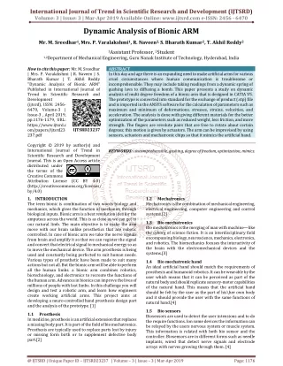
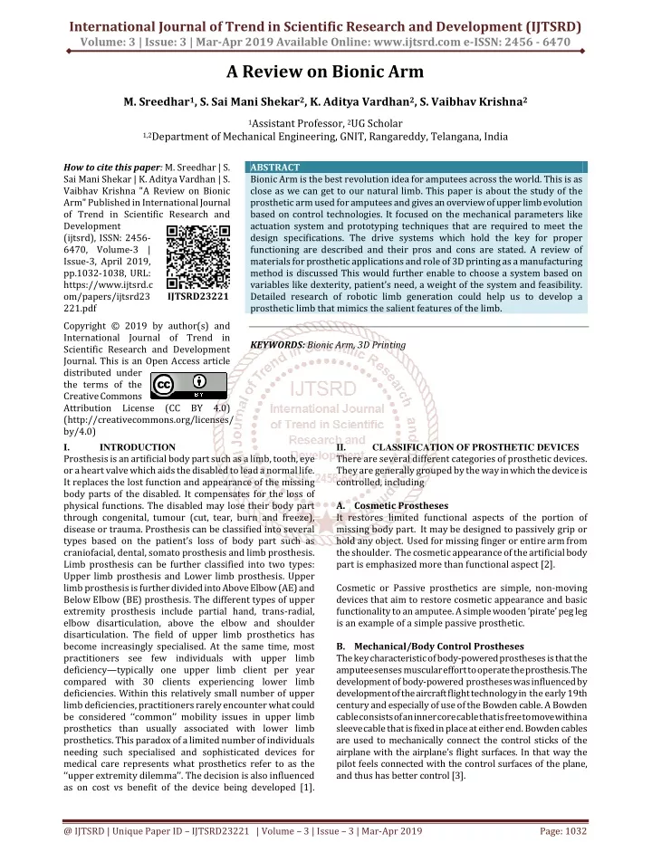
International Journal of Trend in Scientific Research and Development (IJTSRD) Volume: 3 | Issue: 3 | Mar-Apr 2019 Available Online: www.ijtsrd.com e-ISSN: 2456 - 6470 A Review on Bionic Arm M. Sreedhar1, S. Sai Mani Shekar2, K. Aditya Vardhan2, S. Vaibhav Krishna2 1Assistant Professor, 2UG Scholar 1,2Department of Mechanical Engineering, GNIT, Rangareddy, Telangana, India How to cite this paper: M. Sreedhar | S. Sai Mani Shekar | K. Aditya Vardhan | S. Vaibhav Krishna "A Review on Bionic Arm" Published in International Journal of Trend in Scientific Research and Development (ijtsrd), ISSN: 2456- 6470, Volume-3 | Issue-3, April 2019, pp.1032-1038, URL: https://www.ijtsrd.c om/papers/ijtsrd23 221.pdf Copyright © 2019 by author(s) and International Journal of Trend in Scientific Research and Development Journal. This is an Open Access article distributed under the terms of the Creative Commons Attribution License (CC BY 4.0) (http://creativecommons.org/licenses/ by/4.0) I. INTRODUCTION Prosthesis is an artificial body part such as a limb, tooth, eye or a heart valve which aids the disabled to lead a normal life. It replaces the lost function and appearance of the missing body parts of the disabled. It compensates for the loss of physical functions. The disabled may lose their body part through congenital, tumour (cut, tear, burn and freeze), disease or trauma. Prosthesis can be classified into several types based on the patient’s loss of body part such as craniofacial, dental, somato prosthesis and limb prosthesis. Limb prosthesis can be further classified into two types: Upper limb prosthesis and Lower limb prosthesis. Upper limb prosthesis is further divided into Above Elbow (AE) and Below Elbow (BE) prosthesis. The different types of upper extremity prosthesis include partial hand, trans-radial, elbow disarticulation, above the elbow and shoulder disarticulation. The field of upper limb prosthetics has become increasingly specialised. At the same time, most practitioners see few individuals with upper limb deficiency—typically one upper limb client per year compared with 30 clients experiencing lower limb deficiencies. Within this relatively small number of upper limb deficiencies, practitioners rarely encounter what could be considered ‘‘common’’ mobility issues in upper limb prosthetics than usually associated with lower limb prosthetics. This paradox of a limited number of individuals needing such specialised and sophisticated devices for medical care represents what prosthetics refer to as the ‘‘upper extremity dilemma’’. The decision is also influenced as on cost vs benefit of the device being developed [1]. ABSTRACT Bionic Arm is the best revolution idea for amputees across the world. This is as close as we can get to our natural limb. This paper is about the study of the prosthetic arm used for amputees and gives an overview of upper limb evolution based on control technologies. It focused on the mechanical parameters like actuation system and prototyping techniques that are required to meet the design specifications. The drive systems which hold the key for proper functioning are described and their pros and cons are stated. A review of materials for prosthetic applications and role of 3D printing as a manufacturing method is discussed This would further enable to choose a system based on variables like dexterity, patient’s need, a weight of the system and feasibility. Detailed research of robotic limb generation could help us to develop a prosthetic limb that mimics the salient features of the limb. KEYWORDS: Bionic Arm, 3D Printing II. CLASSIFICATION OF PROSTHETIC DEVICES There are several different categories of prosthetic devices. They are generally grouped by the way in which the device is controlled, including A.Cosmetic Prostheses It restores limited functional aspects of the portion of missing body part. It may be designed to passively grip or hold any object. Used for missing finger or entire arm from the shoulder. The cosmetic appearance of the artificial body part is emphasized more than functional aspect [2]. Cosmetic or Passive prosthetics are simple, non-moving devices that aim to restore cosmetic appearance and basic functionality to an amputee. A simple wooden ‘pirate’ peg leg is an example of a simple passive prosthetic. B.Mechanical/Body Control Prostheses The key characteristic of body-powered prostheses is that the amputee senses muscular effort to operate the prosthesis. The development of body-powered prostheses was influenced by development of the aircraft flight technology in the early 19th century and especially of use of the Bowden cable. A Bowden cable consists of an inner core cable that is free to move within a sleeve cable that is fixed in place at either end. Bowden cables are used to mechanically connect the control sticks of the airplane with the airplane’s flight surfaces. In that way the pilot feels connected with the control surfaces of the plane, and thus has better control [3]. IJTSRD23221 @ IJTSRD | Unique Paper ID – IJTSRD23221 | Volume – 3 | Issue – 3 | Mar-Apr 2019 Page: 1032
International Journal of Trend in Scientific Research and Development (IJTSRD) @ www.ijtsrd.com eISSN: 2456-6470 Bowden cables have also been used in bicycle brakes. Body- powered prostheses have not changed much after their introduction in 1950s. Most of the time they were worn with a harness around the shoulders where one or more Bowden cables are attached. The traditional below-elbow, body-powered prosthesis has a single Bowden cable which runs from the harness to the terminal device. Opening of the terminal device is achieved by glenohumeral flexion. Direct Brain Interface III. The most cutting-edge type of control is a direct brain neural interface. A surgical procedure places electrode arrays on the surface of the brain which are attached to pedestals implanted into the patient’s skull. As the patient thinks of motion signals detected on the pedestals are used to control the movement of a robotic arm. This type of technology is still in its infancy but has already demonstrated disabled people controlling bionic devices with their thoughts alone [4]. IV. AVAILABLE ACTUATION PROSTHETIC DEVICES A.Pneumatic System An exceptional feature of pneumatic actuator is its simplicity and convenience. Its working is based on the compressibility of air. The actuator is composed of a rubber balloon, a net that covers the balloon, and a passage that injects compressed air into the balloon. Expanding the rubber balloon shortens the net in the longitudinal direction and thus generates force. The expansion and contraction operations can be controlled by adjusting the pressure in the rubber balloon. But pneumatic actuators are best suited when driven by low-pressure and low-volume of compressed air. It can also fit directly in a prosthetic finger depending upon design compactness [5]. B.Hydraulic Driven The principle of a hydraulically driven actuator is as follows. A liquid is pressed into a cavity that is connected to the levers of a joint. As the volume of the cavity increases the joint levers move apart and an extension is performed. The resulting force and the range of motion depend on the actuator geometry and pressure. These actuators have a very good power to weight ratio and high dynamics. Contrary to conventional actuators the mechanical design of the joint is restricted less by the geometry of the actuator. Other advantages over conventional actuators are the lack of friction in the actuator itself and the lower cost [6]. SYSTEMS IN Fig. 1: Body powered hook C.Myoelectric Controlled Prostheses My electric control systems use muscle electricity as the control method for controlling the prosthesis. My electric control’s distinctive characteristic is that it uses electro my gram (EMG) signals from the stump as inputs to control the upper-limb prosthesis. Surface electrodes placed on the skin near a muscle can detect the electricity produced by contracting muscles at the nearby area. The intensity of the EMG signal produced increases as muscle tension increases. The signal is detected from the surface electrodes, amplified, processed, and then used to control the prosthesis [4]. My electric control first appeared in the 1940s, but it was only until 1970s that it was broadly used in the clinical environment. Today my electric control is a favourite but may not be the best way of fitting upper-limb prostheses. It provides open-loop velocity control which is inferior to position control achieved from a position controller like a power-enhanced extended physiological proprioception (EPP) controller. In my electric control, the input command signal is proportional to the speed of the prosthesis. Visual feedback is the only feedback to inform the amputee of the state of the prosthesis. The advantage of my electric control over power- enhanced EPP control is that my electric require neither a harness nor a cine plastic surgical procedure. My electric control disadvantage over EPP is that it does not provide proprioceptive sensory feedback. In addition, my electric control is velocity control which has been proven to be inferior to position control in positioning tasks. Fig. 3: Initial and Pressurised condition of pneumatic and hydraulic actuators C.Pulley Driven Here the finger is divided into three phalanges, connected by pins and movement of phalanges is defined by cables. A pulley is located at each pin joint. The use of pulleys is to move with fewer friction. However, there is a need of idler pulleys to maintain contact between cables and driving Fig. 2:Schematic diagram of a my electric controller used in an upper limb prosthetics @ IJTSRD | Unique Paper ID - IJTSRD23221 | Volume – 3 | Issue – 3 | Mar-Apr 2019 Page: 1033
International Journal of Trend in Scientific Research and Development (IJTSRD) @ www.ijtsrd.com eISSN: 2456-6470 pulleys. Also, there is chance of gradual wear of cables in the long run. An advantage of this type is the load on the servos is greatly reduced. For actuation purpose generally two routes of cables are opted one for flexion and other for extension of fingers with a combination of springs. The extension routing is provided on the back side [7]. F.Linkage System On careful observation of the human finger we can notice that the first pivot of the finger link moves by a shorter angle as compared to other links. This point justifies the use of mechanism of a four-bar linkage. It is simple and light in weight. The bars are configured in a way that they fold at the same time just moving one bar towards or forwards, with this system you don’t need motors and the manufacturing is easy and cheap. The angle of pin joints and the length of each link determine the range of motion for the fingers. The movements are quite limited as the flexion is produced at the same instant [8]. Fig. 4: Pulley driven mechanism D.Gear Driven The first thing to look after in adapting a geared setup is to keep the transmission system simple and approximate the area required for the drive train and motors. Employing gears opens options for reduction ratios and isolates shocks to individual gear only, hence motor is protected from shocks. First a worm is inserted to the output shaft of a motor then coupled to a spur gear and the final packaging involves power transmission to linkages through final gear. But use of worm gears are inefficient and depends on friction between the input and driven worm gears [8]. Fig. 7: Bar links mechanism G.Tendon Driven Many tendon-driven robotic hands are being developed these days, which are under actuated. The tendon-driven mechanism enables to reduce the weight of the prosthetic robotic hand as they can be actuated with very few actuators. The tendon-driven mechanism imitates the muscles and tendon mechanisms of a human hand. The use of tendons not only allows to reduce the weight, but also gives the benefit of being flexible and back-drivable. More flexibility of finger movement is achieved through the help of tendon-driven mechanism. Plentiful efforts have been put in developing a tendon-driven mechanism for a humanoid robotic hand, but still the dexterity of a natural human being is yet to be achieved [10]. Usually, the tendons must be stiff to achieve full movement of all fingers. Many researchers have suggested incorporating elasticity into robotic actuators. This improves the precision and stability and reduces the end-point position error under load disturbances. Fig. 5: Gear driven mechanism E.Motor Driven A clear alternative over pneumatic and hydraulic systems which demand packaging and controlling issues is a mechanism driven by individual motors. In a general electric motor situation, a constant voltage would have to be applied to a stalled motor in order to produce a constant output force. This system constantly wastes available power. Additionally, almost no electric motors can handle being stalled for even short periods of time. So irrespective of the force required the motor will run continuously. Also, this system adds more weight to the palm, which is not ideal in the case of prosthetics and generally used for robotic applications. A clear advantage of motor driven systems is it increases the DOF’s of the system and eliminates lag during operation [9]. Fig. 8: Tendon driven mechanism H.Flexible Joints System Elastic joints are adapted instead of conventional revolute joints to perform different grasping mechanisms. Such joints are helpful to obtain different shapes and sizes of grips. Elastomers such as urethane rubber are used to produce these soft joints. Advantages of the soft joints are user safety, compliance and adaptability. However, undesired deflections are a common problem which can be overcome by a combination of rigid material with higher stiffness along with the elastic material. Fig. 6: Motor Driven System @ IJTSRD | Unique Paper ID - IJTSRD23221 | Volume – 3 | Issue – 3 | Mar-Apr 2019 Page: 1034
International Journal of Trend in Scientific Research and Development (IJTSRD) @ www.ijtsrd.com eISSN: 2456-6470 Instead of hinged joints, the parts of the fingers can be connected to each other with a flexible joint. The joint was designed to both keep the fingers attached to each other and to maintain the steady position of the hand when not in use [11]. Titanium was discovered in the late 18th century. It is a common metal used for medical and engineering applications because of its many favourable properties. It has good strength to weight ratio, goo strength to density ratio, excellent corrosion resistance, low density and it is lightweight [15]. It is commonly alloyed with other metals to improve certain properties, most commonly aluminium and vanadium. In its unalloyed condition, titanium is as strong as some steels, but less dense. Being lightweight, strong, resistant to corrosion and biocompatibility are its most desirable properties for the application of prosthetics. Its low modulus of elasticity makes it like that of bone. This means that the skeletal load of its user will be distributed relatively evenly between the bone and the implant making for a more natural gait. When its characteristics are well understood and designed properly, this can be a very economical option for the lifetime of the product. B.Polymers Polymers are not often used for as the main load bearing structure for limbs. They are more common with phalanges, joints, and other smaller body parts. When it comes to limb prostheses, polymers are more common for the smaller components or specialized features. Common polymers used are polyoxymethylene (POM), which is a hard polymer, pliable polyurethane (PU), which is much softer, and poly vinyl chloride (PVC), which is used as a coating. Polyethylene is a more flexible form of plastic and it ideally used in larger quantities when the prosthetic needs to be waterproof [17]. The design, fit and material are all highly specialized because it need to be waterproof, capable of performing swim motions, and comfortable while doing so. Everyday prosthetics are not intended to be used in such an environment nor in such a motion. PVC first developed in the early part of the 20th century and by 50s it was one of the most important plastics PVC is very durable but has limited colour range. Silicone resists stains but is less durable. PVC is unstable when exposed to heat and light, so it requires the addition of stabilizers [13]. Ionomeric polymer metal composites (IPMC) are attractive types of electro---active polymer actuation materials because of their characteristics of large electrically induced bending, mechanical flexibility, low excitation voltage, low density, and ease of fabrication [12]. C.Carbon Fibres The use of carbon fibres came about in the 20th century when medics and engineers were in search of a lighter load bearing material. The properties of carbon fibres, such as high stiffness, high tensile strength, low weight, high chemical resistance, high temperature tolerance and low thermal expansion, high specific strength and specific modulus. It was determined that it could be strong enough for even a heavy weight amputee. Materials with high elastic modulus are usually not very ductile: the specific modulus of wood is comparable to that of steel, magnesium, titanium, or aluminum, whereas that of carbon fibre reinforced composites is about three times as high. Carbon fibre reinforced composites also have very high specific tensile and compressive strengths, as well as high responsive elastic deformation [14]. Fig. 9: Elastic Joint Fig. 10: Elastic joint with rigid material reinforcement Fig. 11: Flexible joints COMMON MATERIALS USED FOR PROSTHESIS When beginning to create a new prosthetic, the designer should strongly consider the material and the main load bearing structure. The prosthetics should be light weight yet strong enough for an active and heavy weight amputee [13]. There have been many developments over the years as prosthetics are becoming more and more common. Major material properties to compare and analyse include but are not limited to the following; compressive, torsional, tensile, and shear strength, specific density, energy storage characteristics, stiffness, shock absorption (damping), fatigue resistance, fracture toughness, creep, yield stress, and bio compatibility. All characteristics are being continually improved, and designs are increasingly beginning to reflect the real functions of human limbs [14]. A.Metals A variety of metals are used for prosthetics limbs; Aluminum, Titanium, Magnesium, Copper, Steel, and many more. They are each used in a varied amount and for various applications, either pure or alloyed. Copper, iron, aluminum and nickel have all been used for the load bearing structure in the past but are currently used primarily as alloys or for plating. V. these properties and @ IJTSRD | Unique Paper ID - IJTSRD23221 | Volume – 3 | Issue – 3 | Mar-Apr 2019 Page: 1035
International Journal of Trend in Scientific Research and Development (IJTSRD) @ www.ijtsrd.com eISSN: 2456-6470 The Northrup Aircraft Corporation was doing research after being contracted by the Veteran’s Administration. It was determined that the material was brittle and susceptible to impact damage that was great cause for concern [18]. Carbon fibre can also be costly compared to other material with similar properties. D.Other Materials Biocompatibility refers to materials that are not harmful to living tissue. This is most often considered when making surgical tools or other objects that interact with the body internally. Another aspect of biocompatibility is how a material interacts with the surface of the skin or the external body. When prosthetics are attached to the exterior of the limb, and constant movement is occurring, the skin can be subject to a variety of painful and uncomfortable side effects. The distribution of mechanical stress at body support interfaces can influence the risk of tissue breakdown. Excessive pressure and shear stress can lead to skin blisters, cysts, or ulceration. Interface materials influence the pressure and shear distribution on skin and underlying tissues principally via their elastic property and their frictional characteristics with skin. Other materials used in prosthetics are Spenco, Poron, Nylon---reinforced silicone, Nickelplast, to name a few. These are all commonly used and have been carefully tested and selected based on their performance during compression testing. They have all been evaluated based on their coefficients of friction with some exceptions. Nylon---reinforced silicone was not tested because it tended to crack during shear loading and Spenco was not tested because it became extremely thin after short term loading [16]. VI. MANFUCTURING METHODS A.Conventional Manufacturing Methods One of the conventional manufacturing methods that can be used to manufacture prostheses is machining. It is a method which involves material removal process that is conducted with a cutting tool. Machining used to be one of the main manufacturing methods for fabricating orthopedic implants. Compared with advanced manufacturing technologies, machining is consider as fairly cost effective and user- friendly. It can also be used to improve the surface finish of the finished product. This method is highly recommended for manufacturing implant components with simple designs. The combination of machining parameters can determine the quality of the finished products. Optimum working parameters need to be determined according to the working material in order to achieve the good surface finish. With the development of advanced manufacturing technologies, conventional machining was replaced by computer numerical control (CNC) machining. The aid of CNC has managed to reduce the process duration, making it more user-friendly with a minimum requirement of human input. Micromachining method, on the other hand is a method that uses laser aided technology that can modify the surface structure of polymer components with micro-scale surface texture. It is also applied for manufacturing tiny implant components as well. 5 axis CNC have better flexibility in machining complex geometrical designs as compared to 3- axis CNC machine. The only limitation of machining is the deposition of raw material waste. Incremental sheet forming (ISF) on the other hand is a forming process of sheet metal through continuous forming. This method uses a rotating tool through a progressive increase in pressure and it is adaptable to CNC milling equipment [19]. Other conventional method used for production of prothesis is injection molding. The advantages include short times for production and consistent repeatability. Process involves in this method is heated filament is injected into a metal mold. Parts rarely take longer than 30 seconds to cool, the length of time for entire process is shorter than that of 3D printing. Some disadvantages to this method are high capital cost and complexity. These capital costs are much higher than those for 3D printing. B.Additive Manufacturing Methods One of the best methods for manufacturing prosthetic hand is additive manufacturing commonly referred to as 3D Printing. 3D printing can be used to develop any computer- aided design (CAD) model using thermoplastics such as ABS, PLA and PET. The advantages to 3D printing are customization, simplicity manufacturing (AM) is a manufacturing method by material deposition in layers that build a part based on standard tessellation language (STL) formatted file from computer- aided design (CAD) software. The product of AM can be designed by the digital scan of the part and from the conceptual part design. It is a direct and straightforward method that is more feasible and relevant for manufacturing medical implants. The AM has the flexibility of using a variety of available materials with desired customizations such as porosity and surface roughness as well. There are three types of AM method which are solid based, liquid based and powder-based AM [19]. Fused deposition manufacturing (FDM) is one application of solid based AM that eject thin filament through an extrusion nozzle on a moving platform. The filament is heated at the nozzle to reach a semi-liquid state and then extruded on the platform or on top of previously printed layers. The layer thickness, width and orientation of filaments and air gap (in the same layer or between layers) are the main processing parameters that affect the mechanical properties of printed parts. Inter-layer distortion was found to be the main cause of mechanical weakness. Low cost, high speed and simplicity of the process are the main benefits of FDM. On the other hand, weak mechanical appearance, poor surface quality and a limited number of thermoplastic materials are the main drawbacks of FDM. The development of fibre-reinforced composites using FDM has strengthened the mechanical properties of 3D printed parts. However, fibre orientation, bonding between the fibre and matrix and void formation are the main challenges that arise in 3D printed composite parts [20]. and low cost. Additive properties, layer-by-layer Fig. 12: Schematic diagram of FDM @ IJTSRD | Unique Paper ID - IJTSRD23221 | Volume – 3 | Issue – 3 | Mar-Apr 2019 Page: 1036
International Journal of Trend in Scientific Research and Development (IJTSRD) @ www.ijtsrd.com eISSN: 2456-6470 Powder bed fusion processes consist of thin layers of very fine powders, which are spread and closely packed on a platform. The powders in each layer are fused together with a laser beam or a binder. Subsequent layers of powders are rolled on top of previous layers and fused together until the final 3D part is built. Powder size distribution and packing, which determine the density of the printed part, are the most crucial factors to the efficacy of this method. The laser can only be used for powders with a low melting/sintering temperature, whereas a liquid binder should otherwise be used. Selective laser sintering (SLS) can be used for a variety of polymers, metals and alloy powders while selective laser melting (SLM) can only be used for certain metals such as steel and aluminum. Laser scanning in SLS does not fully melt the powders and the elevated local temperature on the surface of the grain’s results infusion of the powders at the molecular level. On the other hand, the powders are fully melted and fused together after laser scanning in SLM, which results in superior mechanical properties. In the case of using a liquid binder, the method is referred to as three- dimensional printing or 3DP. The chemistry and rheology of the binder, size and shape of powder particles, deposition speed, the interaction between the powder and binder, and post-processing techniques play an important role in 3DP. Laser power and speed of scanning are the main parameters affecting the sintering process. Fine resolution and high quality of printing are the main advantages of powder bed fusion, which make it suitable for printing complex structures and used as the support, which overcomes difficulties in removing supporting material. However, the main drawbacks of powder bed fusion, which is a slow process, include high costs and high porosity when the powder is fused with a binder [20]. production (CLIP) is another modified liquid-based AM that was developed to improve staircase effect. LIP deposits continuous liquid compound that manipulates oxygen- comprised area, known as the ‘dead zone’. It is a small gap in between the oxygen absorbent window and the curing resin. Unlike SLA, CLIP promotes faster building process. This technology is relatively new and can process biological and elastic materials that are suitable for artificial tissue and cartilage [19]. Fig. 14: Schematic diagram of SLA Fig. 15: CLIP Equipment VII. A detailed study of prosthesis hand devices based on controlling system with actuation systems, material requirement and manufacturing method is presented in this work. This enables us to adopt the mechanism based on performance level required and in cases where specific functionality is to be achieved. It also opens the options and gives flexibility to the designer. The pros and cons of the system is also presented. Most frequently used materials in commercial prosthesis is broadly classified into three categories and compared. Though materials are opted on application oriented we can conclude that plastics are best material, especially for hobbyist and testing (experimental) type of applications. Materials that 3D printers are compatible with, print bed temperature, post processing required are the deciding factors in the manufacturing segment. Commercialization of product is an issue with 3D printing as it is time taking. However, Conventional methods are ruled out and 3D printing is emerging as a clear option for prostheses. CONCLUSION Fig. 13: Schematic diagram of powder bed fusion Some of the methods of liquid based AM are stereo lithography (SLA), and continuous liquid interface production (CLIP). SLA’s building process is known as photo polymerization. It is a process of polymer solidification by application of ultraviolet (UV) rays that act as a catalyst for the liquid resin reaction. It is a continuous process of making the part layer by layer until a solid object is constructed. SLA is known to have excellent dimensional accuracy and surface finish for polymer-based products. Due to this advantage, Nano-SLA technology was developed for the purpose of manufacturing micro devices with complex geometry. Furthermore, micro-SLA (MSLA) that was developed could produce fine resolution scaffold with excellent mechanical properties that are like bone. This technology is showing great potential in the fabrication of customized tissue scaffold for cell regeneration. Continuous liquid interface @ IJTSRD | Unique Paper ID - IJTSRD23221 | Volume – 3 | Issue – 3 | Mar-Apr 2019 Page: 1037
International Journal of Trend in Scientific Research and Development (IJTSRD) @ www.ijtsrd.com eISSN: 2456-6470 A brief study of manufacturing methods is given which allows to choose based on factors like printer accessibility, cost, robustness etc. Additive Manufacturing proves to be promising due to its material saving nature, considerably good mechanical properties, surface finish, and ability to manufacture complex geometries. REFERENCES [1]Angana Saikia, Sushmi Mazumdar, Nitin Sahai, Sudip Paul, Dinesh Bhatia, Suresh Verma & Punit Kumar Rohilla, “Recent advancements in prosthetic hand technology” in Journal of Medical Engineering & Technology, 21 Apr 2016, pp. 1-2. International Conference on Intelligent Robots and Systems. Human Robot Interaction and Cooperative Robots, 1995, vol. 1, pp. 399-406. [11]Andiy Sayuk, Mahmoud Tavakoli, Pedro Neto “Compliant joints with rigid materials: additive manufacturing of geometrical features for the applications of grasping”, submitted for possible publication in “ASME journal of Mechanisms and Robotics”, September 2015, pp. 12. [12]Aravinthan. P & Gopala Krishnan. N & Srinivas. P. A & Vigneswaran. N. “Design, Implementation of Neurologically Controlled Prosthetic Limb Capable of Performing Rotational Movement”, 2010. Development and [2]Tushar Kulkarni, Rashmi Uddanwadiker, “Mechanism and Control of a Prosthetic Arm”, Article in Molecular and cellular biomechanics, MCB, Vol.0, no.0, pp.1-49, 2015. [13]Smith, M. J., & Kirk, S., & Tate, J., & Cox, D. Material Characterization and preservation guidance for a collection of prosthetic limbs developed since 1960. Studies in Conservation, 2014. [3]Georgios A. Bertos, Evangelos G. Papadopoulos, “Upper Limb Prosthetic Devices”, chapter six in Handbook of Biomechatronics, 2019, pp. 182-184. [14]Gutfeisch, O, Peg legs and bionic limbs: the development of lower extremity prosthetics, Maney for the Institute of Materials, Minerals and Mining, 2003. [4]Duke SciPol, “Brain-Computer Interface based Neuro- prosthetics” available online 19 May 2017 at http://scipol.duke.edu/content/brain-computer- interface-based-neuro prosthetics. [15]Hanson, B. H, Present and Future uses of Titanium in Engineering, Materials & Design, 1986, pp. 301-307. [5]Hiroyuki Takeda, Nobutaka Tsujiuchi, Takayuki Koizumi, Hiroto KanMasanori Hirano, Yoichiro Nakamura, “Development of Prosthetic Arm with Pneumatic Prosthetic Hand and Tendon-Driven Wrist” in 31st Annual International Conference of the IEEE EMBS Minneapolis, Minnesota, USA, September 2-6, 2009, pp. 5048. [16]Sanders, J.E., & Greve, J. M. & Mitchell, S. B., & Zachariah, S. G. “ Material properties of commonly---use interface materials and their static coefficients of friction with skin and socks”, in Journal Of Rehabilitation Research & Development, pp. 161. [17]Schreiber, N. S., & Gettens, R. T. T. “Aquatic Design for Individuals with Disabilities: Upper Limb Prosthesis”, Department of Biomedical Engineering, Western New England University. [6]Schulz, Christian Pylatiu, Markus Reischl, Jan Martin, Ralf Mikut and Georg Bretthauer, “A hydraulically driven multifunctional prosthetic hand”,Robotica, Volume 23, Issue 03, May 2005, pp. 293 – 299. [18]Shorter, J. J, “Carbon Fibers-Uses and Prospects. Proceedings of the 3rd PRI International Conference Carbon Fibres 3. [7]Umar Farooq, M. Zulqarnain Khalid, Talha Wahab Umar Shahbaz, Javaid Iqbal, “Mechanical design of a tendon activated prosthetic hand”, October 2012, pp. 1-2. [19]Ahmad Majdi Abdul Rani, Rosdayanti Fua- Nizan, Mohamad Yazid Din, Abdul Azeez Abdu Aliyu, “Manufacturing Method for Medical Prostheses- A Review” in International Medical Device and Technology Conference 2017, pp. 138-140. [8]Paul Ventimiglia (LA&E) , Professor Taskin Padir , Professor Jerome Schaufeld, “Design of a Human Hand Prosthesis”, 2015, pp. 20-22. [9]Universitat de Lleida ,Escola Politècnica .Superior Grau d’Enginyeria Mecànica, “Design and implementation of a bionic arm”, pp. 17. [20]Tuan D. Ngo, Alieza Kashani, Gabriekle Imbalzano, Kate T.Q. Nguyen, David Hui, “Additive manufacturing (3D printing): A review of materials, methods, applications and challenges”, June 2018, pp. 173-175. [10]G. A. Pratt and M. M. Williamson, & quot; Series Elastic Actuators,& quot; in Proceedings 1995 IEEE/RSJ @ IJTSRD | Unique Paper ID - IJTSRD23221 | Volume – 3 | Issue – 3 | Mar-Apr 2019 Page: 1038