Download
1 / 4
40 likes | 49 Vues
This research work is based on design and construction of a floor cleaning robot with two modes automatic and manual mode. It supports automatic mode in this paper. IR sensor is used to avoid the obstacles and change left direction after right direction and it is mounted at the front side of the robot. It is applied to meet the U turn movement for complete coverage navigation by using optocoupler based encoder feedback. In this system, two motors 555 dc gear motor are used with L298 for robot movement, and other 12V dc motor is used with MOSFET driver to control the speed of the cleaner. The wireless connection between remote control and robot is established by using RF module. In U paths, the robot moves forward direction and turn left if it is detected wall and turn left again and move forward direction. Battery percentage, cleaner speed, movement of the robot and selected mode are displayed on the LCD. ATmega328P microcontroller based Arduino UNO board are applied as the heart of the system. Simulation test and experimental test are utilized for stable response in domestic application. Kyawt Kay Thwe | Zaw Myo Tun "Automatic Floor Cleaning Robot using Encoder" Published in International Journal of Trend in Scientific Research and Development (ijtsrd), ISSN: 2456-6470, Volume-3 | Issue-5 , August 2019, URL: https://www.ijtsrd.com/papers/ijtsrd25253.pdf Paper URL: https://www.ijtsrd.com/engineering/electronics-and-communication-engineering/25253/automatic-floor-cleaning-robot-using-encoder/kyawt-kay-thwe<br>

E N D
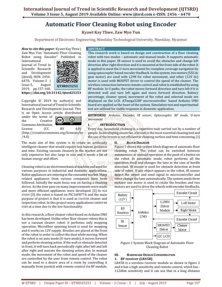
International Journal of Trend in Scientific Research and Development (IJTSRD) Volume 3 Issue 5, August 2019 Available Online: www.ijtsrd.com e-ISSN: 2456 – 6470 Automatic Floor Cleaning Robot using Encoder Kyawt Kay Thwe, Zaw Myo Tun Department of Electronic Engineering, Mandalay Technological University, Mandalay, Myanmar How to cite this paper: Kyawt Kay Thwe | Zaw Myo Tun "Automatic Floor Cleaning Robot using Encoder" Published in International Journal of Trend in Scientific Research and Development (ijtsrd), ISSN: 2456- 6470, Volume-3 | Issue-5, August 2019, pp.157-160, https://doi.org/10.31142/ijtsrd25253 Copyright © 2019 by author(s) and International Journal of Trend in Scientific Research and Development Journal. This is an Open Access article distributed under the terms of the Creative Commons Attribution License (CC (http://creativecommons.org/licenses/by /4.0) The main aim of this system is to create an artificially intelligent cleaner that would require less human guidance and time. Existing vacuum cleaners in the market are not only expensive but also large in size and it needs a lot of human energy and effort. Cleaning robot is an electromechanical machine and used for various purposes in industrial and domestic applications. Robot appliances are entering in the consumer market. Many related appliances from various companies have been followed. Initially the main focus was on having a cleaning device. As the time pass on many improvements were made and more efficient appliances were developed.[2]In OLD STUDY [3],the robot is based on PIC16F877A and the main purpose of project is that it is used as VACUUM cleaner and inspection robot. In this project many applicationS CANNOT BE USED at a time due to the low functionality. In this research, a floor cleaner robot based on Arduino UNO has been developed. Unlike other floor cleaner robots this is not a vacuum cleaner robot: it performs only mopping operation. Microfiber spinning brush is used for mopping and it works on 12V supply. Brushes are placed at the front of the robot in order to collect the dust while moving. When the robot is on auto mode (U-turn mode), it moves forward and perform cleaning action. If the wall or obstacle detected in front, it will turn back periodically right after left and left after right and execute the cleaning action also. In manual mode, the movement of the robot and speed of the cleaner are controlled by the user from remote control. The robot can be used to a desire area of a room by controlling it manually from joystick with remote control via RF module. ABSTRACT This research work is based on design and construction of a floor cleaning robot with two modes – automatic and manual mode. It supports automatic mode in this paper. IR sensor is used to avoid the obstacles and change left direction after right direction and it is mounted at the front side of the robot. It is applied to meet the U-turn movement for complete coverage navigation by using optocoupler based encoder feedback. In this system, two motors (555 dc gear motor) are used with L298 for robot movement, and other (12V dc) motor is used with MOSFET driver to control the speed of the cleaner. The wireless connection between remote control and robot is established by using RF module. In U paths, the robot moves forward direction and turn left if it is detected wall and turn left again and move forward direction. Battery percentage, cleaner speed, movement of the robot and selected mode are displayed on the LCD. ATmega328P microcontroller- based Arduino UNO board are applied as the heart of the system. Simulation test and experimental test are utilized for stable response in domestic application. KEYWORDS: Arduino, Encoder, IR sensor, Optocoupler, RF mode, U-turn movement I. INTRODUCTION Every day, household cleaning is a repetitive task carried out by a number of people. In developing countries, a broom is the most essential cleaning tool and the use of the broom is not efficient in cleaning surface and time consuming. [1] II. BLOCK DIAGRAM Figure 1 shows the system block diagram of automatic floor cleaning robot. The robot can be switched between autonomous or manual operation at the push of a button on the robot. In automatic mode, robot performs all the operation itself and changes the lane in the case of hurdle detection. IR sensor is used for obstacle detection at front side of robot. If any object appears in the robot, IR sensor detect the object and send signal to microcontroller and robot change the lane automatically. The system needs three motors- one motor is used to rotate the brushes and two motors are used to drive the wheels with encoder feedbacks. IJTSRD25253 BY 4.0) Figure 1 System Block Diagram of Automatic Floor Cleaning Robot HARDWARE DESIGN CONSIDERATION 1.RF receiver (LR45B) LR45B is a wireless receiver module as shown in figure 2 and it has a high sensitivity and remote control, which has - 112dbm sensitivity and it can use that in a long distance III. @ IJTSRD | Unique Paper ID – IJTSRD25253 | Volume – 3 | Issue – 5 | July - August 2019 Page 157
International Journal of Trend in Scientific Research and Development (IJTSRD) @ www.ijtsrd.com eISSN: 2456-6470 reaching up to 200m. The module has a small size, low power consumption and it can save the space and energy. It has voltages between 4.5V and 5.5V, its frequency is 433MHz which has a peak current of 5mA. This module has maximum receiving rate of 4.8kbps.[4] 4.Encoder reading For detection the pulses from left and right wheels, ITR9813 as shown in Figure 5 module is applied. The ITR9813 consist of an infrared emitting diode and an NPN silicon phototransistor, encased side-by-side on converging optical axis in a black thermoplastic housing so that the phototransistor receives radiation from the IR LED only. Figure 2 RF Receiver (LR45B) Figure 5 ITR9813 optocoupler 2.ArduinoUNO Arduino UNO is used for transmitter side. It is a microcontroller board based on the Atmega328p. It has 14 digital input/output pins (of which 6 can be used as PWM outputs), 6 analog inputs, a 16 MHz quartz crystal. Figure 3 shows the circuit diagram of transmitter circuit. Pin 2,3,4 and 5 are used for digital reading for cleaner speed up, cleaner speed down, U-turn activation and U-turn deactivation. Four 10kΩ resistors are used for pull-down which cause LOW state when the buttons are not press. For radio transmission, 433MHz radio transmitter is used. It is connected to Arduino hardware serial transmit pin. Joystick module has two potentiometers and they are scanned by A0 and A1 pin of Arduino UNO. Two of 3.7V batteries are used for power and build-in 5V 1A regulator generate 5V for switches, potentiometer and RF transmitter.[5] When encoder does not allow between IR and phototransistor, phototransistor will be off and output at collector will be HIGH stage. If there is a light between then, phototransistor will be on and collector voltage will be in LOW voltage. Figure 6 Square wave transformation circuits for ITR9813 Although ITR9813 gives good response in the form of square wave at low frequencies, it gives round shape at higher frequency and it cannot be directly connected into interrupt pins of microcontroller. The square wave transformation circuit is needed to compare that round wave with a constant DC voltage. It can be solved using LM358N operational amplifier in open-loop non-inverting comparator mode as shown in Figure 6. 5.Robot Driving Motors Figure 3 Arduino UNO microcontrollers 3.IR sensor module This module is inexpensive solution for an obstacle avoidance sensor, perfect for robotic projects and very easy to interface directly with Arduino and compatible boards. It also works with two potentiometers one to control frequency and the other to control the intensity.[6] It includes 4 pins header as shown in figure 4. Figure 7 TAKANAWA 555 Metal Gear Motor DC gear motor shows in figure 7 that has specific features- high speed, high torque, low power consumption and low noise. The module has simple machine structure, easy maintenance and long service life. The specification of DC gear motor up to 80 rpm,1 2V 2.5A maximum draw. [7] Figure 4 IR Sensor module @ IJTSRD | Unique Paper ID – IJTSRD25253 | Volume – 3 | Issue – 5 | July - August 2019 Page 158
International Journal of Trend in Scientific Research and Development (IJTSRD) @ www.ijtsrd.com eISSN: 2456-6470 6.CleanerMotor V. The user can start the cleaner for manual mode or U-turn mode by switching on the remote control. Serial communication of 1200 bps is applied to meet RF module recommendation. At receiver, 1200 bps is used for matching as transmitter side. Figure 11 represents U-turn movement. It will check IR sensor for obstacle or wall. Whenever it detects wall, check encoder 1 and 2. If encoder 1 is less than140, the robot will turn left and encoder 2 is less than 140, the robot will turn right. In this system 140 encoder pulse makes a full turn back movement. After turning back, IR sensor will be check again and it will drive forward until it doesn’t detect obstacle. SOFTWAREDESIGN IMPLEMENTATION Figure.8 Gearmotors JGY370 Worm Gearmotor For cleaning operation, gear DC motor with micro-turbine worm is applied. DC gear motor show in figure 8 can be rated to 150 rpm at 12V and 24 kg.cm torque. [8] IV. HARDWARE DESIGN CONSIDERATION Figure 9 Circuit diagram of Floor Cleaning Robot The L298N is used for driving two DC motors for vehicle at the same time. The module can drive DC motors that have voltages between 5 and 35V, with a peak current up to 2A. The input 1 and input 2 pins are used for controlling the rotation direction of the left side motor, and the inputs 3 and 4 for the right side motor. The switches of the H-bridge inside the L298N IC can be controlled by using these pins. If input 1 is LOW and input 2 is HIGH and the motor will move forward, and vice versa, if input 1 is HIGH and input 2 is LOW and the motor will move backward. In case both inputs are same, either LOW or HIGH the motor will stop. The same applies for the inputs 3 and 4 and the motor B. A0, A1, A2 and A3 pins (or pin 14, 15, 16 and 17 pins) are used for above two motor. IRFZ4N n-channel MOSFET transistor is designed to switch heavy DC loads from a PWM pin of Arduino. Its main purpose is to provide a low cost way to drive a DC motor for the robotics applications. IRFZ44N can be used up to 55V and 49A current draw which is well enough for 12V 2.5A cleaner motor. PCF8574 based I2C (Inter-integrated Communication) LCD (Liquid Crystal Display) is applied for system monitoring. A4 and A5 pins support SDA (Serial Data) and SCL (Serial Clock) of I2C communication. RF receiver module is attached to digital pin 7 in which Software Serial communication is setup for signal receiving. IR sensor is attached to digital pin4 for obstacle and wall detection. Arduino UNO has 2 interrupt pins and they are applied for encoder reading as shown in Figure 9. Figure10 Flowchart for U-turn Movement VI. The program is written using Arduino IDE (Integrated Development Environment) and the serial debugger is applied for computer-based debugging. For I2C (Inter- Integrated Communication) LCD (Liquid Crystal Display), PCF8574 I2C module and 16x2 line LCD is applied in this simulation as shown in following figures 11. It represents U- turn mode, encode pulse values and battery voltage are displayed on the second line of LCD display. At the interrupt pins of Arduino, square wave input is attached for examining encoder counter. The newest PWM value is displayed on LCD before “/255” value. SIMULATIONTEST @ IJTSRD | Unique Paper ID – IJTSRD25253 | Volume – 3 | Issue – 5 | July - August 2019 Page 159
International Journal of Trend in Scientific Research and Development (IJTSRD) @ www.ijtsrd.com eISSN: 2456-6470 Figure.14 Encoder and Battery Level Display in U-turn Mode VII. The results in section V show that encoder based robot can also be used for exact turning action in floor cleaning robot. Advantages of this robot are well support not only for turning movement of U-turn algorithm but also in pattern like motion in short time period. This system is designed both automatic and manual mode with minimum supervision. It works on 12V supply and can be used 3 hours. It can be charged within an hour. A brush is placed at the front and it can be changed a new brush easily. Manual mode helps to clean the particular place and save the energy of the human. In automatic mode, the use of a floor cleaner can reduce labor cost as well as time. Further, the robot can be moved U pattern which navigate a cleaner through a room to complete coverage navigation. ACKNOWLEDGMENT The author would like to thank all the teachers from the Department of Electronic Technological University (M.T.U). And she also would like to thank her family and her friends who have helped her during this research work. And also, thank for Dr. Tin Tin Hla, Head of the department. REFERENCES [1]P. B. Jarande, S. P. Murakar, N. S. Vast,N. P. Ubale and S. S. Saraf “Robotic Vacuum Cleaner Using Arduino with wifi” international Conference on Inventive Communication and Computational ART;ISBN:978-1-5386-1974-2 DISCUSSIONAND CONCLUSION Figure 11 Simulation Result for U-turn Mode In this paper, the robot moves along a straight line for vertical movement of U-turn path planning as shown in figure 12. Engineering, Mandalay Figure.12 planning path for U-turn Technologies, CFP18BAC- [2] Prof. Taware R. D., Vaishali Hasure, Puja Ghule, Komal Shelke, “Design and Development of Floor Cleaner Robot (Automatic and Manual Mode)”, 2017 IJRTI | Volume 2, Issue 4 | ISSN: 2456-3315 [3]Prof. PriyaShukla and Mrs. Simmy S.L. “Design and Inspection of cleaning robot.” Issued volume 3, Issued 6 sept 2014. [4]https://www.fasttech./com/product/5457400-lr45b- 433mhz-ask-wireless-remote-control-receiver [5]https://www.tomsonelectronics.com/blogs/news/Ardu ino-uno-specification [6]https://www.jaycarcom.au/medias/sys_master/images /9229278773278/XC4524-dataSheetMain.pdf Figure13 Experimental Setup for Robot Hardware construction of floor cleaner is showed in figure 13. The LCD display with encoder value and battery voltage level is displayed in Figure 14. The robot can be used in public places as hospitals, libraries, schools and shop. [7]https://sea.banggood.com/TAKANAWA-555-Metal- Gear-Motor-12V-24V-DC-Gear-Motor-p- 995307.html?cur_warehouse=CN [8]https://www.seeedstudio.com/ASLONG-JGY-370-12V- DC-Worm-Gear-Motor-p-1887.html @ IJTSRD | Unique Paper ID – IJTSRD25253 | Volume – 3 | Issue – 5 | July - August 2019 Page 160