Download
1 / 5
50 likes | 60 Vues
The most important aim of the project is to make use of the active vibration control technique to reduce vibration in composite shaft system using three nodded beam element. The fiber reinforced polymer FRP composite shaft is deliberate in this paper considering it as a Timoshenko beam. Three dissimilar isotropic rigid disks are mounted on it and also supported by two active magnetic bearings at its split ends. The work involves finite element, vibration and rotor dynamic analysis of the structure. Rotary inertia effect, gyroscopic effect kinetic energy and strain energy of the shaft are derived and studied. The governing equation is obtained by applying Hamilton's principle using finite element method in which four degrees of freedom at each node is considered. Active control scheme is applied through magnetic bearings by using a controller containing low pass filter, notch filter, sensor and amplifier which controls the current and correspondingly control the stability of the whole rotor shaft system. Campbell diagram, steadiness limit speed diagram and logarithmic decrement diagram are considered to establish the system stability. Effect of different types of stacking sequences are also studied and compared Jay Krishn Yadav | H. S. Sahu "Design, Optimization and Analysis of a Radial Active Magnetic Bearing for Vibration Control" Published in International Journal of Trend in Scientific Research and Development (ijtsrd), ISSN: 2456-6470, Volume-3 | Issue-4 , June 2019, URL: https://www.ijtsrd.com/papers/ijtsrd24040.pdf Paper URL: https://www.ijtsrd.com/engineering/mechanical-engineering/24040/design-optimization-and-analysis-of-a-radial-active-magnetic-bearing-for-vibration-control/jay-krishn-yadav<br>

E N D
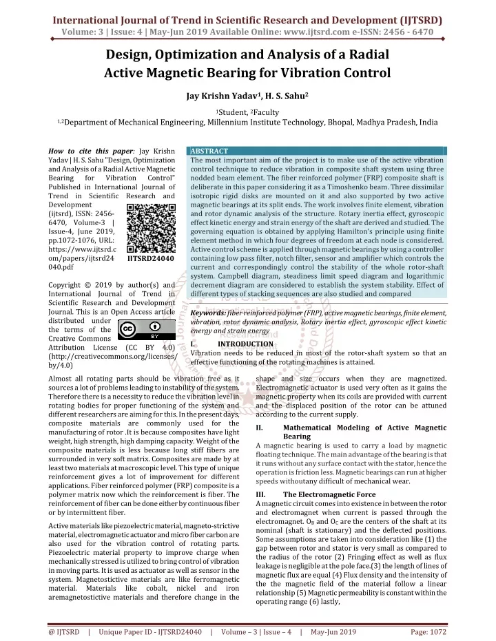
International Journal of Trend in Scientific Research and Development (IJTSRD) Volume: 3 | Issue: 4 | May-Jun 2019 Available Online: www.ijtsrd.com e-ISSN: 2456 - 6470 Design, Optimization and Analysis of a Radial Active Magnetic Bearing for Vibration Control Jay Krishn Yadav1, H. S. Sahu2 1Student, 2Faculty 1,2Department of Mechanical Engineering, Millennium Institute Technology, Bhopal, Madhya Pradesh, India How to cite this paper: Jay Krishn Yadav | H. S. Sahu "Design, Optimization and Analysis of a Radial Active Magnetic Bearing for Vibration Published in International Journal of Trend in Scientific Research and Development (ijtsrd), ISSN: 2456- 6470, Volume-3 | Issue-4, June 2019, pp.1072-1076, URL: https://www.ijtsrd.c om/papers/ijtsrd24 040.pdf Copyright © 2019 by author(s) and International Journal of Trend in Scientific Research and Development Journal. This is an Open Access article distributed under the terms of the Creative Commons Attribution License (CC BY 4.0) (http://creativecommons.org/licenses/ by/4.0) Almost all rotating parts should be vibration free as it sources a lot of problems leading to instability of the system. Therefore there is a necessity to reduce the vibration level in rotating bodies for proper functioning of the system and different researchers are aiming for this. In the present days, composite materials are commonly used for the manufacturing of rotor .It is because composites have light weight, high strength, high damping capacity. Weight of the composite materials is less because long stiff fibers are surrounded in very soft matrix. Composites are made by at least two materials at macroscopic level. This type of unique reinforcement gives a lot of improvement for different applications. Fiber reinforced polymer (FRP) composite is a polymer matrix now which the reinforcement is fiber. The reinforcement of fiber can be done either by continuous fiber or by intermittent fiber. Active materials like piezoelectric material, magneto-strictive material, electromagnetic actuator and micro fiber carbon are also used for the vibration control of rotating parts. Piezoelectric material property to improve charge when mechanically stressed is utilized to bring control of vibration in moving parts. It is used as actuator as well as sensor in the system. Magnetostictive materials are like ferromagnetic material. Materials like aremagnetostictive materials and therefore change in the ABSTRACT The most important aim of the project is to make use of the active vibration control technique to reduce vibration in composite shaft system using three nodded beam element. The fiber reinforced polymer (FRP) composite shaft is deliberate in this paper considering it as a Timoshenko beam. Three dissimilar isotropic rigid disks are mounted on it and also supported by two active magnetic bearings at its split ends. The work involves finite element, vibration and rotor dynamic analysis of the structure. Rotary inertia effect, gyroscopic effect kinetic energy and strain energy of the shaft are derived and studied. The governing equation is obtained by applying Hamilton’s principle using finite element method in which four degrees of freedom at each node is considered. Active control scheme is applied through magnetic bearings by using a controller containing low pass filter, notch filter, sensor and amplifier which controls the current and correspondingly control the stability of the whole rotor-shaft system. Campbell diagram, steadiness limit speed diagram and logarithmic decrement diagram are considered to establish the system stability. Effect of different types of stacking sequences are also studied and compared Keywords: fiber reinforced polymer (FRP), active magnetic bearings, finite element, vibration, rotor dynamic analysis, Rotary inertia effect, gyroscopic effect kinetic energy and strain energy I. INTRODUCTION Vibration needs to be reduced in most of the rotor-shaft system so that an effective functioning of the rotating machines is attained. Control" IJTSRD24040 shape and size occurs when they are magnetized. Electromagnetic actuator is used very often as it gains the magnetic property when its coils are provided with current and the displaced position of the rotor can be attuned according to the current supply. II. Mathematical Modeling of Active Magnetic Bearing A magnetic bearing is used to carry a load by magnetic floating technique. The main advantage of the bearing is that it runs without any surface contact with the stator, hence the operation is friction less. Magnetic bearings can run at higher speeds withoutany difficult of mechanical wear. III. The Electromagnetic Force A magnetic circuit comes into existence in between the rotor and electromagnet when current is passed through the electromagnet. OB and OC are the centers of the shaft at its nominal (shaft is stationary) and the deflected positions. Some assumptions are taken into consideration like (1) the gap between rotor and stator is very small as compared to the radius of the rotor (2) Fringing effect as well as flux leakage is negligible at the pole face.(3) the length of lines of magnetic flux are equal (4) Flux density and the intensity of the the magnetic field of the material follow a linear relationship (5) Magnetic permeability is constant within the operating range (6) lastly, cobalt, nickel and iron @ IJTSRD | Unique Paper ID - IJTSRD24040 | Volume – 3 | Issue – 4 | May-Jun 2019 Page: 1072
International Journal of Trend in Scientific Research and Development (IJTSRD) @ www.ijtsrd.com eISSN: 2456-6470 IV. A controller is used here for the active control of the FRP rotor shaft system. In the controller there are several actions take place that should be taken under consideration for proper modeling of the system and to get an appropriate transfer function. One bearing consists of four pairs of electromagnetic pole which are placed around the periphery of the rotor in a symmetric way. Only two control axes along Y and Z direction are considered for the control purpose. Figure (3) is showing a block diagram for a radial dynamic magnetic bearing with the controller and other electronic devices like sensor and amplifier. There are changed types of operations take place within the controller to achieve a proper control of magnetic bearing stability. The reference signal is set to zero in the AMB system to align the rotor within the axes of the rotor. Hence this particular input feed can be discounted in the controller function. The director used here is a digital electronic device. Therefore the position signal coming out from the differential sensor in the voltage form is required to be changed into digital form before sending it to the system controller. An analog to digital converter is used for taken as 2a=45. shown in the Fig.1 Controller is connected with the bearing and offers active vibration and stability control of the whole system. Bias current for each of the magnets within the magnetic bearing is 0.75this purpose. The process of digitization does not affect the overall control of the system, therefore it is ignored. A simplified one, neglecting the open loop control, signal injection, analog-digital converter and digital-analog converter which are discussed above. The signal taken as a orientation is first set to a zero value. Therefore this system input is ignored and the position input is taken in consideration as well. The stiffness and damping coefficient can be determined from the feed through transfer function, G(s), which is discussed above in the section. Hence a simplified block diagram to find out axis stiffness and damping coefficient values. Mathematical Modeling of Controller V. The rotor with AMB, used for the numerical simulation is shown in the figure (5.1). A complete programming is developed using MATLAB 13a to analyze the effectiveness of active control method on the stability of the FRP rotor shaft system. The shaft is loaded with three dishes and is supported with the help of two identical orthotropic bearings. bearingarek Results and Discussions = 1.75×10⁷N/m, s/m, czz= 500 N s/m. Fig. 1. Block diagram showing the closedloop control for single axis AMB. Amps which more closely mimics a power-limited system. A nominal gap of 0.381 mm is maintained initially when no vibration takes place. A low pass filter with a cutoff frequency of 800 Hz and a damping ratio of 0.7 is used along with a PID filter with very low gains to initially levitate the system .A notch filter is also used to dampen out high frequency resonance. It is used at a frequency of 200 Hz which is substantially higher than the first critical speed of the controlled system. Table.1 Parameters of FRP composite shaft system Parameter Length Diameter(mm) Density Coefficient ofviscous damping Coefficint of hysteretic damping Eccentricity (m) Shear correction factor Mass of disc(kg) Longitudinal Young’s Modulus (GPa) Transverse Young’s Modulus (GPa) Poisson’sRatio0.313 Shaft 1.2 100 1578 0.0002 0.0002 0.56 139 11 0.313 Disk1 Disk 2 Disk 3 0.0002 0.0002 0.0002 45.947 45.947 45.947 VI. The comparisons between the controlled and uncontrolled responses of the FRP composite shaft system are clearly shown in the Fig.2, Fig.3. and Fig.4.These results are obtained by using the stacking sequence[90/45/45/0/0/0/0/0/90]. Comparison Between Controlled and Uncontrolled Responses In the uncontrolled response of the FRP composite shaft system, the bearing stiffness and damping is present along with internal viscous and hysteretic damping of the shafts. On the other hand in the uncontrolled response, additional stiffness and damping values are added to the system in an active way with the use of an active controller discussed earlier. The Campbell diagram shown in the Fig.2 clearly exhibits that the critical speed of the uncontrolled shaft system is around 3045 rpm, which is increased up to 3814 rpm when active control technique is applied. @ IJTSRD | Unique Paper ID - IJTSRD24040 | Volume – 3 | Issue – 4 | May-Jun 2019 Page: 1073
International Journal of Trend in Scientific Research and Development (IJTSRD) @ www.ijtsrd.com eISSN: 2456-6470 Figure 3 shows the variation of damping ratio of the controlled and uncontrolled rotor- bearing system. Six natural modes are being shown where we see that the damping ratio in the uncontrolled case becomes negative around 13600 rpm. Figure 4 shows the same fact that the stability limit speed can reach up to 13580 rpm with active control system in place. Fig.2. Comparison of the controlled system fig.2. (a)and fig.2. (b.) Campbell diagram for uncontrolled system. Fig.3.Variation of damping ratio of first six modes for controlledfig 3(a.)system and fig 3(b.). uncontrolled system. @ IJTSRD | Unique Paper ID - IJTSRD24040 | Volume – 3 | Issue – 4 | May-Jun 2019 Page: 1074
International Journal of Trend in Scientific Research and Development (IJTSRD) @ www.ijtsrd.com eISSN: 2456-6470 Effect of Stacking Sequences In Table No.2 different stacking sequences are taken under consideration. In symmetric stacking sequence the stability limit value changes from 2535 rpm to 2627 rpm when active magnetic bearing control is applied. The first critical speed also variations its value from 2405 rpm to 2765 rpm. In anti-symmetric stacking sequence the critical Fig.4.Variation of maximun real part of the eigenvalueswith rotational speed Hence it does not affect the stability of the system. Uncontrolled Controlled Stability Limit Speed (Rpm) 2535 3192 8651 11260 Stability Limit Speed(Rpm) 2627 3655 9908 13580 Critical Speed (Rpm) 2405 2731 2630 3045 Table No.5.2Comparison of different stacking Critical Speed (Rpm) 2765 3250 3112 3814 Stacking Sequence [90/90/45/0/0]S [45/0/45/0/90]AS [0/90/0/90/0/90/0/90/0/90] [90/45/45/0/0/0/0/0/0/9] speed value increases to 3250 rpm from 2731 rpm while stability limit speed increase to 3655 rpm from 3192 rpm. In the cross sequencing the critical speed variations from 2630 rpm to 3112 rpm. On the other hand stability limit speed rises from 8651 rpm to 9908 rpm. For the stacking sequence of [90/45/45/0/0/0/0/0/0/90] the controlled response of the FRP composite shaft system is also shown in the table. The critical speed in this case increases from 3045 rpm to 3814 rpm and stability limit speed from 11260 rpm to 13545 rpm. VII. Conclusion From the above results it may be concluded that the active magnetic bearing used in the rotor-shaft system where rotor is made up of fiber reinforced polymer (FRP) composite, brings the system into a stable position. The active technique is achieved by bringing a controller into the picture which senses the displacement and controls the corresponding current in order to achieve stability. The different parameters of PID filter are tuned manually to get the optimum results. The Campbell diagrams prove that the critical speed of the controlled system has been increased to a higher value and the stability limit speed (SLS) diagrams show that the system can run at much superior speed when operate with active control method. The active magnetic bearing also provide a contact-free procedure which reduce rotor vibration. The control action is free from the problem of maintenance, wear and tear and power loss due to friction. VIII. ?Functionally graded materials (FGM) can be used in place of composite material for the shaft. ?The effect of temperature can also be analyzed to see the variation of the results with respect to different temperature distribution. ?The effect of stresses induced in the lamina of the composite shaft can also be analyzed. References [1]GauravKumar,“Design and Analysis of a Radial Active Magnetic Bearing for Vibration”, vol. 175(6), (2016). Scope of Future Work [2]Singh.S.P.,Gupta.K. “Composite Shaft Rotordynamic analysis using a layerwise theory”, Journal of Sound and Vibration, vol. 191(5), pp. 739-756,(2016). [3]Kim.W.,Argento.A., and Scott.R.A “Free Vibration of a Rotating Tapered Composite Shaft System”, Journal of Sound and Vibration, vol. 226(1), pp. 125-147,(2015). @ IJTSRD | Unique Paper ID - IJTSRD24040 | Volume – 3 | Issue – 4 | May-Jun 2019 Page: 1075
International Journal of Trend in Scientific Research and Development (IJTSRD) @ www.ijtsrd.com eISSN: 2456-6470 [4]Chang.M.Y.,Chen.J.K., and Chang.C.Y. “A simple Spinning Laminated Composite Shaft Model”, International Journal of Solids and Structures, vol. 41, pp. 637- 662,(2015). analysis, design, and technology”, IEEE Trans Control Systems Tech, vol.13, no.4, (2012),pp.559-576. [13]Foeppl A., Der Civilingenieur, “Das Problem der Delaval‟schenTurbinenvelle” (2012). [5]Ghoneam.S.M.,Hamada.A.A., “Dynamic Analysis of Composite Shaft”,Department of Production Engineering and Mechanical Design, Menoufia University,Egypt (2015). and El-Elamy.M.I. [14]Stodola A., “NeveKristischeDrehzahlenalsfolye der kreiselwirkuag der laufrader” GesanteTubinenwes, 15, (2011), PP.269–275. [15]Jeffcott H. H., “The lateral vibration of loaded shafts in the neighbourhood of the whirling speeds”, Philosophical magazine, vol. 37, (2011), pp.304-315. [6]Boukhalfa.A., “Dynamic Analysis of a Spinning Laminated CompositeShaft Using the hp- Version of the Finite Element Method”, Department of Mechanical Engineering, University of Tlemcen,Algeria (2014). [16]Kirk R. G., Gunte E. J., “the effect of support flexibility and damping on the synchronous response of a single mass flexible rotor”, J. Eng. Ind., Trans. ASME (2010) pp.221–232. [7]Richardet.G.J.,Chatelet.E., and Baranger.T.N. “Rotating Internal Damping in the Case of Composite Shaft”, University de Lyan, CNRS, INSA-Lyan, LaMCoS UMR5259, VelleurbanneF-69621,France(2014).. [17]Nelson, H.D. and McVaugh, J.M., “The Dynamics of Rotor-bearing Systems Using Finite Elements,” ASME Journal of Engineering for Industry, Vol. 98,No.2, ( 2010), pp. 593- 600. [8]Chang.M.Y.,Chen.J.K., Chang.C.Y., “A simple spinning laminated composite shaft model”, Department of Mechanical Engineering, HsingUniversity,Taiwan(2014).. National Chung [18]Schweitzer G., Bleuler H.A. “Traxler, Active Magnetic Bearings”,Schweitzer G., “Magnetic bearing for vibration control”, publicationInternational Conference on Engineering Optimization, Rio de Janeiro, Brazil, June (2009), pp.1 - 5 [9]Nelson.F.C., “Rotor Dynamics without Equation”, Professor of Mechanical Engineering, Tuffts University, Medford, MA 02155,USA. (2013). in: NASA Conference [10]Perini E.A., Bueno D. D., Santos R. B., Junior V. L., NascimentoLuiz MachineryVibrationControlBasedonPolesAllocationusi ngMagneticActuators”,International Conference on Engineering Optimization, Rio de Janeiro, Brazil, June (2013), pp.1 -5 de P. “Rotating [19]Bennett, engineering”,(2009). Stuart “A history of control [20]Ang K.H., Chong G.C.Y., and Li Y. “PID control system analysis, design, and technology”, IEEE Trans Control Systems Tech, vol.13, no.4, (2008),pp.559-576. [11]Bennett, engineering”,(2012). Stuart “A history of control [21]Stodola A., “NeveKristischeDrehzahlenalsfolye der kreiselwirkuag der laufrader” GesanteTubinenwes, 15, (2008), P.269–275. [12]Ang K.H., Chong G.C.Y., and Li Y. “PID control system @ IJTSRD | Unique Paper ID - IJTSRD24040 | Volume – 3 | Issue – 4 | May-Jun 2019 Page: 1076