Download
1 / 8
100 likes | 131 Vues
In the present scenario welding of dissimilar metals is very important because one metal cannot gives optimum chemical, physical and mechanical properties required for an application. Like Al Steel or Mg Al welding for reducing the weight of the transportation vehicles such as train, automobile, and ship, high alloy material low alloy steel or stainless steel low carbon steel for strength and corrosion resistance, Al Cu for electronic components. So many researches have been carried out on joining of Fe Al by RSW using different elements as interlayer but optimization of cladding ratio for transition material is not done. Here in this paper condition for optimum performance is determined in the terms of influence of parameters on the tensile shear strength of the weld, optimize the process parameters without the Silver interlayer, optimize the process parameters with the Silver interlayer, and investigate the mode of failure of these welds. Vikash Siddhu | Naveen Kumar | Dr. Navneet Arora "Investigation on Dissimilar Metal Welds by Resistance Spot Welding Process" Published in International Journal of Trend in Scientific Research and Development (ijtsrd), ISSN: 2456-6470, Volume-2 | Issue-3 , April 2018, URL: https://www.ijtsrd.com/papers/ijtsrd10805.pdf Paper URL: http://www.ijtsrd.com/engineering/mechanical-engineering/10805/investigation-on-dissimilar-metal-welds-by-resistance-spot-welding-process/vikash-siddhu<br>

E N D
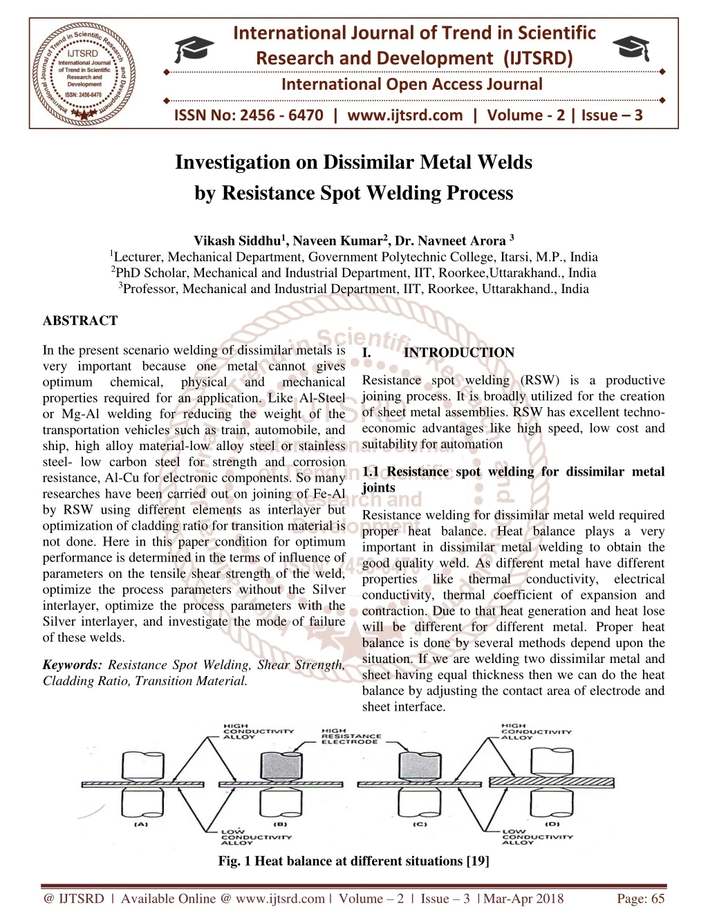
International Journal of Trend in Scientific Research and Development (IJTSRD) International Open Access Journal ISSN No: 2456 - 6470 | www.ijtsrd.com | Volume - 2 | Issue – 3 Investigation on Dissimilar Metal Welds by Resistance Spot Welding Process Vikash Siddhu1, Naveen Kumar2, Dr. Navneet Arora 3 1Lecturer, Mechanical Department, Government Polytechnic College, Itarsi, M.P., India 2PhD Scholar, Mechanical and Industrial Department, IIT, Roorkee,Uttarakhand., India 3Professor, Mechanical and Industrial Department, IIT, Roorkee, Uttarakhand., India ABSTRACT In the present scenario welding of dissimilar metals is very important because one metal cannot gives optimum chemical, physical and mechanical properties required for an application. Like Al-Steel or Mg-Al welding for reducing the weight of the transportation vehicles such as train, automobile, and ship, high alloy material-low alloy steel or stainless steel- low carbon steel for strength and corrosion resistance, Al-Cu for electronic components. So many researches have been carried out on joining of Fe-Al by RSW using different elements as interlayer but optimization of cladding ratio for transition material is not done. Here in this paper condition for optimum performance is determined in the terms of influence of parameters on the tensile shear strength of the weld, optimize the process parameters without the Silver interlayer, optimize the process parameters with the Silver interlayer, and investigate the mode of failure of these welds. INTRODUCTION I. Resistance spot welding (RSW) is a productive joining process. It is broadly utilized for the creation of sheet metal assemblies. RSW has excellent techno- economic advantages like high speed, low cost and suitability for automation 1.1 Resistance spot welding for dissimilar metal joints Resistance welding for dissimilar metal weld required proper heat balance. Heat balance plays a very important in dissimilar metal welding to obtain the good quality weld. As different metal have different properties like thermal conductivity, electrical conductivity, thermal coefficient of expansion and contraction. Due to that heat generation and heat lose will be different for different metal. Proper heat balance is done by several methods depend upon the situation. If we are welding two dissimilar metal and sheet having equal thickness then we can do the heat balance by adjusting the contact area of electrode and sheet interface. Keywords: Resistance Spot Welding, Shear Strength, Cladding Ratio, Transition Material. Fig. 1 Heat balance at different situations [19] @ IJTSRD | Available Online @ www.ijtsrd.com | Volume – 2 | Issue – 3 | Mar-Apr 2018 Page: 65
International Journal of Trend in Scientific Research and Development (IJTSRD) ISSN: 2456-6470 A-Electrode with smaller face area used for high- conductivity alloy. B-High electrical resistance electrode used for high conductivity alloy. joint of H220 Zn-coated high strength steel and 6008 aluminium alloy was mainly composed of η-Fe2Al5 and θ -FeAl3 phases, and the morphology and thickness of the intermetallic compound layer varied with the locations along the interface in the weld. The formation and growth of the intermetallic compounds (η-Fe2Al5 and θ -FeAl3) were controlled by reactive diffusion between solid steel and liquid aluminium alloy during resistance spot welding. C-Same as B with addition of larger electrode face used for low conductivity material. D-Increase thickness of0high conductivity0work piece. Resistance spot welding with interlayer a study done by Zhang et al. [8] on the H220YD0galvanised high strength steel to 60080aluminium alloy by Intermediate frequency RSW using a Alsi12 inter layer at the interface of steel and aluminium. They have found that thickness of intermetallic compound layer is decreasing by the application of inter layer. Due to that strength of the weld is increased considerable as compare to other methods. Eggeleret al. [10] found that Si can reduce the formation and growth of intermetallic layer in the Iron aluminium joining. As we know that from the above discussion that Fe2Al5 and FeAl3 type compound are form in the reaction layer or in intermetallic compound layer of Fe and Al [8]. First FeAl3 type compound is generated at the interface and after that Fe2Al5 type of compound is formed by the diffusion of Al atom to the solid aluminium through the FeAl3. As Fe2Al5 have a orthorhombic structure, when we used Si in the interlayer the Si atoms are then fitted into the vacancies of Fe2Al5 in the c-direction and reduced the diffusion of Al atoms in to that. Due to this reason thickness of One other problem with dissimilar metal joining is that of plasticity temperature range of metals. If plasticity temperature range of two metals is largely differing, then they are difficult to weld. One of the major problems of dissimilar metal joining is formation of brittle intermetallic compounds. As they are brittle in nature due to which strength of the joint reduced. II. LITERATURE REVIEW The joining of Al-Fe is not an easy task. There welding is tough due the having lot of difference in the properties like melting point temperature, coefficient of thermal expansion and contraction, thermal conductivity, electrical resistivity. The one of the major problem is formation of brittle intermetallic compound layer at the interface. According to SeyedehNooshinMortazaviet al. [1] who has perform an experiment on low carbon0steel and A52500aluminium alloy by using RSW, there is formation a brittle intermetallic layer who deteriorate the tensile strength of the weld. The formation of intermetallic0compound limited0solubility of Iron in Aluminium and vice versa. Only small amounts of iron0can be dissolved0in aluminium, and only small amounts of aluminium can be0dissolved in0iron. Iron and aluminium form various intermetallic phases of low0strength and low0toughness. The intermetallic compounds "which are available on it" are gathered as Fe-rich mixes (FeAl and Fe3Al) and Al-rich mixes (FeAl2, Fe2Al5, and FeAl3). Along with these stable compounds, metastable compounds (FeAl6, Fe2Al9, and FeAlx) have been also form in Al/steel interface. layer is due to 2.1 Gaps in Literature Review After doing the detail study of the literature, the following gaps are found: 1.Few literatures are available on joining of Fe-Al by RSW using different elements as interlayer. 2.In the literature cladding ratio optimization for transition material is not clear. 3.In the joining of Fe-Al by using 4047 AlSi12 interlayer the effect of electrode force and weld time is not explained properly. According to W.H. ZHANG et al. [7] who has performed an experiment on H220 Zn-coated high strength steel and 6008 aluminium alloy by RSW find that the intermetallic steel/aluminium interface in resistance spot welded 4.Joining of Fe-Al by using interlayer with the cover plate has not been tried. compound layer at @ IJTSRD | Available Online @ www.ijtsrd.com | Volume – 2 | Issue – 3 | Mar-Apr 2018 Page: 66
International Journal of Trend in Scientific Research and Development (IJTSRD) ISSN: 2456-6470 5.Different materials (Ti, Ag, Cu, Ca, Mg) as interlayer has not been used. 4. To investigate the mode of failure of these welds. III. METHODOLOGY 2.2 Objective of this research 3.1 Material selection 1. To study the influence of parameters on the tensile shear strength of the weld. A 1.0 mm thick Stainless steel (304) sheet with yield0strength and ultimate tensile strength of 215 and 505 MPa, and 1.5 mm thick aluminium(A5052) sheet with yield strength and ultimate tensile strength of 89.6 and 193 MPa was used in the research work. A Silver interlayer of 100µm thickness was also used. The thickness of stainless steel sheet was taken different due to the heat balance during welding. Table 1 Composition of SS 304 2. To optimize the process parameters without the Silver interlayer 3. To optimize the process parameters with the Silver interlayer. SS(304) Wt% C Cr Ni Mn P S Si Fe .04 18.3 9.1 1.2 .03 .01 .5 60.82 Table 2 Composition of Aluminium 5052 alloy 5052 Al Cr Cu Fe Mg Mn Wt% 97.24 0.16 .02 .2 2.5 .08 3.2 Welding Machine Spot welding was performed using a 150KVA AC Pedestal type Resistance Spot Welding Machine. Welding was done using a 45° truncated cone RWMA class 2 electrode. The face diameter of Electrode was 10mm as shown in fig 3.1. The Electrode was made by tapper turning on the lath machine. Fig.2 Resistance spot welding machine 3.3 Sample Preparation Static tensile shear test samples were prepared according to ANSI/AWS/SAE/D8.9-97 standard [Fig. 3]. The samples were prepared with the help of shearing Machine. Firstly samples were polished up to 1200 grit size and then cleaning was done by acetone. Fig 3.3 shows the sample before the cleaning and Fig. 4 shows the sample after the cleaning. @ IJTSRD | Available Online @ www.ijtsrd.com | Volume – 2 | Issue – 3 | Mar-Apr 2018 Page: 67
International Journal of Trend in Scientific Research and Development (IJTSRD) ISSN: 2456-6470 Fig. 3 Weld Samples before the cleaning. Fig.4 Weld sample after cleaning. Fig. 5 Static tensile shear test sample 2. Design the Experiment according to partial/ full fraction design. 3.Conducts the experiments. 4.Analyse the results with the ANOVA to determine the optimum conductions parameter. 5.Run a confirmatory test using the optimum conditions. 3.4 Welding Parameters Taguchi technique involves five steps these are as follows: and significant 1.Find out the best parameters which affect the shear strength. Table 3 Spot welding Parameters for with and without Silver layer and there levels for DOE Levels 2 14 16 Factors Process parameter Unit 1 13 15 3 15 17 1 2 Welding Current Weld Time kA Cycle Same array was used for the spot welding with silver interlayer and the comparisons have been done between them. Table 4.L9 Orthogonal array for spot welding with and without silver interlayer. S.N. Welding Current Weld Time 1 2 3 4 5 6 7 8 9 13 13 13 14 14 14 15 15 15 15 16 17 15 16 17 15 16 17 Fig. 6 Sample after weld @ IJTSRD | Available Online @ www.ijtsrd.com | Volume – 2 | Issue – 3 | Mar-Apr 2018 Page: 68
International Journal of Trend in Scientific Research and Development (IJTSRD) ISSN: 2456-6470 3.5 Metallography Preparation 3.6 Shear Strength Testing Metallography observation was performed on the cross section structure of the weld zone. For this weld was cut from the centre and then cross section was polished up to 2000 grit size. After that cloth polishing with MgO powder. The etchant for steel was aqua regia and for aluminium was Keller’s etchant. Shear strength testing was performed on the Universal Testing Machine. 3.7 Metallographic Observation Metallographic Observation was performed by using the Stereoscopic microscope, Scanning Electron Microscope and FE-SEM. (190ml Distilled Water, 5ml Nitric Acid, 3ml Hydrochloric Acid, and 2ml Hydrofluoric Acid). The etching time was 12 second for aluminium and 1.5 minute for steel. After etching FESEM, EDX and stereoscopy were performed. 3.8 X- Ray Diffraction XRD of fracture surface was performed to know the type of intermetallic formed at the interface of the joint. IV. RESULTS AND DISCUSSIONS 4.1 Influence of welding current on nugget diameter of weld. 12 10 8 Nugget 6 diameter in mm 4 2 0 9 10 11 12 13 14 15 Welding current in kA Series1 Fig 7: Influence of welding current on nugget diameter of weld. Fig 8: Relationship between input parameter and tensile shear strength. @ IJTSRD | Available Online @ www.ijtsrd.com | Volume – 2 | Issue – 3 | Mar-Apr 2018 Page: 69
International Journal of Trend in Scientific Research and Development (IJTSRD) ISSN: 2456-6470 Fig 9: Effect of input parameters on SN ratio Fig. 10 FESEM Micrograph of weld cross section at 15 kA current and 16 cycles weld time. Fig. 11 Fracture of weld during cross sectional cutting of weld. Table 5 Elements and their weight % at the interface of the weld. S.N. 1 3 4 5 6 7 8 Element C Al Si Cr Fe Ni Ag Weight% 11.15 26.76 0.63 8.56 34.90 4.67 1.83 Atomic% 26.17 27.95 0.64 4.64 17.62 2.24 0.48 Fig. 12 XRD Graph of aluminium side fracture surface. @ IJTSRD | Available Online @ www.ijtsrd.com | Volume – 2 | Issue – 3 | Mar-Apr 2018 Page: 70
International Journal of Trend in Scientific Research and Development (IJTSRD) ISSN: 2456-6470 4.2 FESEM Results with Silver Interlayer Fig.13 FESEM micrograph of weld cross section with Silver interlayer at 15 kA current and 16 cycles weld time Fig 14 Fracture surface of Aluminium SS304 joint with Silver interlayer at 39x magnification Fig. 15 Fracture Surface of steel aluminium joint with Silver interlayer at 100X @ IJTSRD | Available Online @ www.ijtsrd.com | Volume – 2 | Issue – 3 | Mar-Apr 2018 Page: 71
International Journal of Trend in Scientific Research and Development (IJTSRD) ISSN: 2456-6470 Fig. 16 XRD Graph of aluminium side fracture surface with Silver interlayer. V. CONCLUSIONS REFERENCES 1.J. Bruckner, C. Writer, Considering thermal processes for http://www.thefabricator.com/Metallurgy/Metallur gy_Article.cfm?ID=676. 2.R. Qiu, C. Iwamoto, S. Satonaka, Mater charac,Vol.60,(2009),p.156. 3.T. Watanabe, A. Yanagisawa, S. Konu Ma, Y. Doi, Weld Int,Vol.20(2006),p.290. 4.Recommended Practices for Test Methods and Evaluation the Resistance Spot Welding Behavior of Automotive Sheet Steels, ANSI/AWS/SAE D8.9-97. 5.P. Marashi, M. Pouranvari, S. Amirabdollahian, A. Abedi, M. Goodarzi, Mater. Sci Eng. A, Vol.480 (2008),p.175. 6.M. Pouranvari , H. R. Asgari, S. M. Mosavizadeh, P. Marashi, M. Goodarzi, Sci.Technol. Weld. Joining, Vol.12(2007) p.217. 7.M. Pouranvari, A. Abedi, P. Marashi , M. Goodarzi, Sci. Technol. Vol.13(2008) p.39. 8.Alper, Allen M Ed, Phase diagrams: Material Science and Technology, 1970, 2.43. 9.[M. J. Rathod, M. Vol.84(2004),p.16s. On the basis of the experimentation and results acquired through analysis of Tensile Shear testing, Metallographic observations, Nugget diameter, EDX, and XRD of fractured surfaces the following can be concluded: •Welding of Steel and Aluminium is a challenging task. These welds show lower tensile shear strength due to formation of intermetallic compounds at the interface of the weld which are brittle in nature like FeAl3, Fe2Al5. •Welding current has the maximum effect on shear strength of the weld joint. •Welding of SS304 with Aluminium 5052 using Silver as an interlayer, Silver reduces the formation of Fe-Al based intermetallic and replace it with Al-Ag based intermetallic, such as Ag2Fe2, Ag2Al, which are ductile in nature. •FESEM micrographs shows a mix mode of fracture. •Welding of SS304 with Aluminium 5052 without using Silver interlayer shows maximum tensile shear strength 4.2 kN. •Welding of SS304 with Aluminium 5052 using Silver as an interlayer shows maximum tensile shear strength 4.6 kN which is higher than welding without Silver interlayer. •The EDX results support the presence of Silver at the weld interface. •In the XRD analysis, mainly FeAl2, FeAl3, Fe2Al5 intermetallic compound and Ag2Al, Ag3Fe2 ductile phases of Al-Ag and Fe-Ag are found. dissimilar metals, Weld. Joining, Kutuna, Weld. J., @ IJTSRD | Available Online @ www.ijtsrd.com | Volume – 2 | Issue – 3 | Mar-Apr 2018 Page: 72