Download
1 / 4
50 likes | 71 Vues
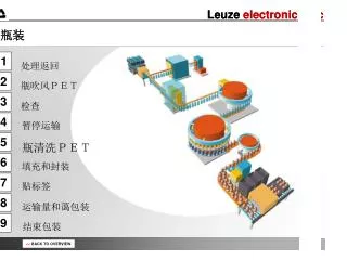
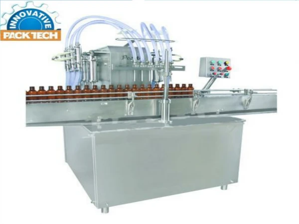
Filling is the task that is carried out by a machine and this process is widely used in many industries that produce such as milk industries, chemical, food, mineral water and many industrial manufactures. The objective of this paper is to design, develop and monitor "Bottle filling and capping with PLC". This work provides with a lot of benefits like low power consumption, low operational cost, less maintenance, accuracy and many more. A prototype has been developed to illustrate the system. In this paper, the filling of the bottle is controlled by using a controller known as Programmable Logic Controller PLC which is also the heart of the entire system. For the conveyor system, a DC motor has been selected for better performance and ease of operation. Proximity sensors have been used to detect the position of the bottle. Ladder logic has been used for the programming of the PLC, which is the most widely used and accepted language for the programming of the PLC. Zar Kyi Win | Tin Tin Nwe "PLC Based Automatic Bottle Filling and Capping System" Published in International Journal of Trend in Scientific Research and Development (ijtsrd), ISSN: 2456-6470, Volume-3 | Issue-6 , October 2019, URL: https://www.ijtsrd.com/papers/ijtsrd28114.pdf Paper URL: https://www.ijtsrd.com/engineering/electrical-engineering/28114/plc-based-automatic-bottle-filling-and-capping-system/zar-kyi-win<br>

E N D
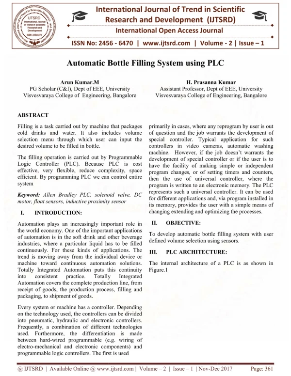
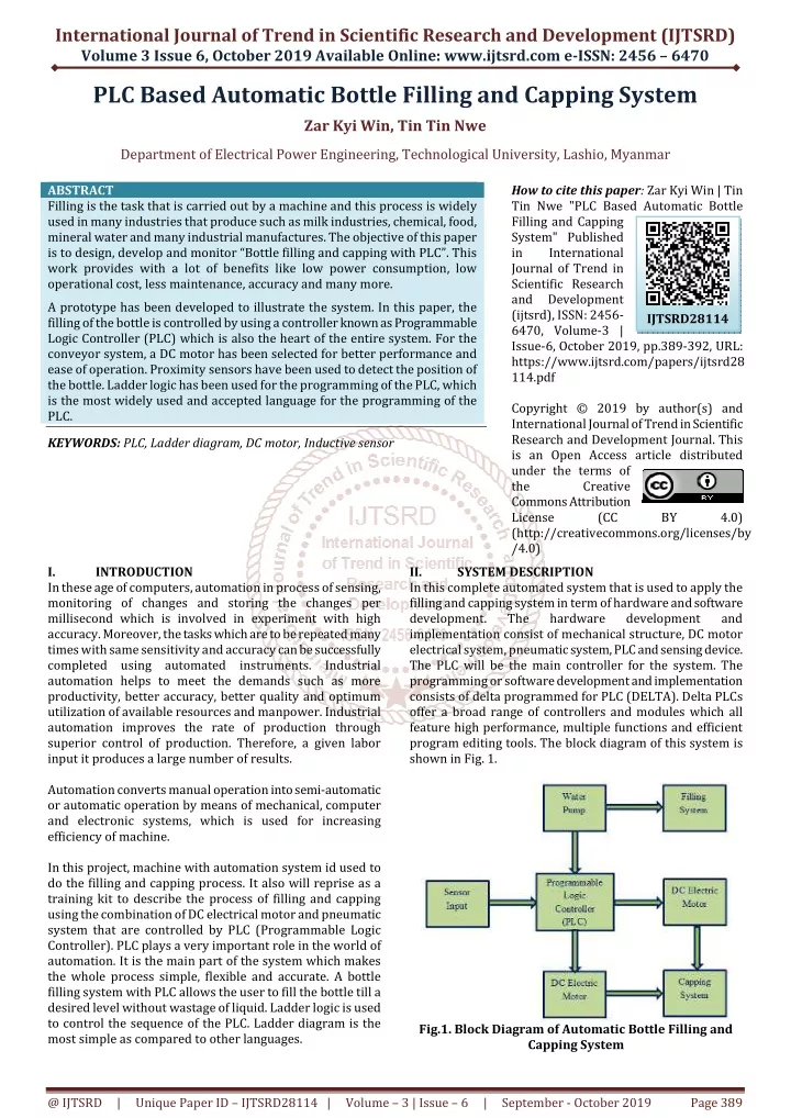
International Journal of Trend in Scientific Research and Development (IJTSRD) Volume 3 Issue 6, October 2019 Available Online: www.ijtsrd.com e-ISSN: 2456 – 6470 PLC Based Automatic Bottle Filling and Capping System Zar Kyi Win, Tin Tin Nwe Department of Electrical Power Engineering, Technological University, Lashio, Myanmar ABSTRACT Filling is the task that is carried out by a machine and this process is widely used in many industries that produce such as milk industries, chemical, food, mineral water and many industrial manufactures. The objective of this paper is to design, develop and monitor “Bottle filling and capping with PLC”. This work provides with a lot of benefits like low power consumption, low operational cost, less maintenance, accuracy and many more. A prototype has been developed to illustrate the system. In this paper, the filling of the bottle is controlled by using a controller known as Programmable Logic Controller (PLC) which is also the heart of the entire system. For the conveyor system, a DC motor has been selected for better performance and ease of operation. Proximity sensors have been used to detect the position of the bottle. Ladder logic has been used for the programming of the PLC, which is the most widely used and accepted language for the programming of the PLC. KEYWORDS: PLC, Ladder diagram, DC motor, Inductive sensor How to cite this paper:Zar Kyi Win | Tin Tin Nwe "PLC Based Automatic Bottle Filling and Capping System" Published in International Journal of Trend in Scientific Research and Development (ijtsrd), ISSN: 2456- 6470, Volume-3 | Issue-6, October 2019, pp.389-392, URL: https://www.ijtsrd.com/papers/ijtsrd28 114.pdf Copyright © 2019 by author(s) and International Journal of Trend in Scientific Research and Development Journal. This is an Open Access article distributed under the terms of the Creative Commons Attribution License (CC (http://creativecommons.org/licenses/by /4.0) SYSTEM DESCRIPTION In this complete automated system that is used to apply the filling and capping system in term of hardware and software development. The hardware implementation consist of mechanical structure, DC motor electrical system, pneumatic system, PLC and sensing device. The PLC will be the main controller for the system. The programming or software development and implementation consists of delta programmed for PLC (DELTA). Delta PLCs offer a broad range of controllers and modules which all feature high performance, multiple functions and efficient program editing tools. The block diagram of this system is shown in Fig. 1. IJTSRD28114 BY 4.0) I. In these age of computers, automation in process of sensing, monitoring of changes and storing the changes per millisecond which is involved in experiment with high accuracy. Moreover, the tasks which are to be repeated many times with same sensitivity and accuracy can be successfully completed using automated instruments. Industrial automation helps to meet the demands such as more productivity, better accuracy, better quality and optimum utilization of available resources and manpower. Industrial automation improves the rate of production through superior control of production. Therefore, a given labor input it produces a large number of results. Automation converts manual operation into semi-automatic or automatic operation by means of mechanical, computer and electronic systems, which is used for increasing efficiency of machine. In this project, machine with automation system id used to do the filling and capping process. It also will reprise as a training kit to describe the process of filling and capping using the combination of DC electrical motor and pneumatic system that are controlled by PLC (Programmable Logic Controller). PLC plays a very important role in the world of automation. It is the main part of the system which makes the whole process simple, flexible and accurate. A bottle filling system with PLC allows the user to fill the bottle till a desired level without wastage of liquid. Ladder logic is used to control the sequence of the PLC. Ladder diagram is the most simple as compared to other languages. INTRODUCTION II. development and Fig.1. Block Diagram of Automatic Bottle Filling and Capping System @ IJTSRD | Unique Paper ID – IJTSRD28114 | Volume – 3 | Issue – 6 | September - October 2019 Page 389
International Journal of Trend in Scientific Research and Development (IJTSRD) @ www.ijtsrd.com eISSN: 2456-6470 III. A.Programmable Logic Controller (PLC) A programmable logic controller (PLC) is a digital electronic device that uses a programmable memory to store instructions and to implement functions such as logic, sequencing, counting, and arithmetic in order to control machines, process, and has been specifically designed to make programming easily. HARDWARE DESCRIPTION Fig.4. DC Motor C.Proximity Sensor Proximity sensors detect the presence or absence of objects using electromagnetic fields, light, and sound. There are many types, each suited to specific applications and environments. In this system, it used inductive and capacitive sensors, the types of proximity sensor. Inductive sensors are used to detect the presence of bottles in the holder. Depending on the output of the sensors the filling and capping operation take place. Fig.5. Proximity Sensor Fig.2. PLC Process Diagram D.12V DC Relay A relay is an electrically operated or electromechanical switch composed of an electromagnet, an armature, a spring and a set of electrical contacts. PLCs consist of input modules or points, a Central Processing Unit (CPU), and output modules or points. An input accepts a variety of digital or analog signals from various field devices (sensors) and converts them into a logic signal that can be used by the CPU. The CPU makes decisions and executes control instructions based on program instructions in memory. Output modules convert control instructions from the CPU into a digital or analog signal that can be used to control various field devices (actuators). A programming device is used to input the desired instructions. These instructions determine what the PLC will do for a specific input. An operator interface device allows process information to be displayed and new control parameters to be entered. Fig.6. 12 V DC Relay The electromagnetic switch is operated by a small electric current that turns a larger current on or off by either releasing or retracting the armature contact, thereby cutting or completing the circuit. Relays are necessary when there must be electrical isolation between controlled and control circuits, or when multiple circuits need to be controlled by a single signal. The output signal from the PLC is given through a relay driver unit which drives the output devices by supplying optimum voltage required for their operation. E.Limit Switch In electrical engineering a limit switch is a switch operated by the motion of a machine part or presence of an object. They are used for controlling machinery as part of a control system, as a safety interlocks, or to count objects passing a point. Fig. 3. PLC Unit (DELTA) B.DC Motor A DC motor like we all know is a device that deals in the conversion of electrical energy to mechanical energy. The main use of DC motor in this system is for the conveyor system with the help of belt to transfer the bottle from one place to another. The motor works on 12 V DC supply. @ IJTSRD | Unique Paper ID – IJTSRD28114 | Volume – 3 | Issue – 6 | September - October 2019 Page 390
International Journal of Trend in Scientific Research and Development (IJTSRD) @ www.ijtsrd.com eISSN: 2456-6470 Fig.7. Limit Switch F.Timer Time delay relays are simply control relays with a time delay built in. Their purpose is to control an event based on time. The difference between relays and time delay relays is when the output contacts open and close: on a control relay, it happens when voltage is applied and removed from the coil; on time delay relays, the contacts can open or close before or after some time delay. Fig.8. Timer G.Water Pump Water pump is electrical units with motors that are sealed to allow them to be submerged. They can be used for purposes such as driving an under gravel filter, or for basic aquarium water circulation, they are economical, fairly inexpensive, and can be beneficial to the health of your aquarium in many ways. Water pump is used for water filling system. It is easier to fill water in the bottle and used the instead of solenoid valve. Fig.11. Ladder Diagram of the Proposed System Of the various languages one can use to program a PLC, ladder logic is the only one directly modeled after electromechanical relay systems. It uses long rungs laid out between two vertical bars representing system power. Along the rungs are contacts and coils, modeled after the contacts and coils found on mechanical relays. The contacts act as inputs and often represent switches or push-buttons; the coils behave as outputs such as a light or a motor. Table 1 shows the operation of Input/ Output Module and Timer of the system. Table1. Input/ Output Module and Timer Input Module Output Module Timer X0 X1 X2 X3 X4 X5 Input Modules: Output Modules: X0 - Start Y0 – Conveyor X1 - Fill Sensor Y1-Filling System X2-Cap Sensor Y2 – Rotate X3-Stop Y3 - Capping System X4-Position M0 - Stop Capping X5-Bottle Out Fig.9. Water Pump IV. WPL Software Version 2.38 is the main programming software which is used to program the PLC. Five distinct forms of programming language for PLC are: ?Ladder Diagram (LD) ?Structured Text (ST) ?Instruction List (IL) ?Function Block Diagram (FBD) ?Sequential Function Chart (SFC). SOFTWARE DESCRIPTION Y0 Y1 Y2 Y3 M0 T0 T1 Timers: T0 – For Filling T1-For Capping Fig.10. WPL Software Version 2.38 @ IJTSRD | Unique Paper ID – IJTSRD28114 | Volume – 3 | Issue – 6 | September - October 2019 Page 391
International Journal of Trend in Scientific Research and Development (IJTSRD) @ www.ijtsrd.com eISSN: 2456-6470 V. IMPLEMENTATION OF BOTTLE FILLING AND CAPPING SYSTEM A.Bottle Detection Using Sensor Bottles are kept in position in their respective holders which are fixed to the conveyor at the input side. Inductive sensors are used to detect the presence of bottles in the holder. Depending on the output of the sensors the filling and capping operation take place. A time delay is given in order to set the status of the bottles. If bottle 1 is present the corresponding status bit in PLC is set to 1 else it is set to 0. The outputs of these sensors are given to the PLC and depending on this output the filling and capping process for the bottles takes place. Thus if all the n bottles are present in the input side then the sensor gives the corresponding output to the PLC which in turn switches ON the corresponding pumps for filling operation to take place. If a particular bottle is not present the corresponding pumps remain OFF. The bottles are transported to the capping arrangement. Inductive sensors are kept to stop the bottles in the desired position for capping to take place. Once the bottles reach the position the conveyor motor switches OFF. The capping of bottles is done using actuator arrangement. Three actuators which move in forward and reverse directions are used to cap the bottles. The actuator applies a force on the caps which are placed in their respective holders. This force helps the caps to fit into the bottles at the required position. Similar to filling, if a particular bottle is not present it does not get capped. Thus the capping is done and the conveyor starts moving again. When the capping operation for one batch is done simultaneously the filling operation for another batch takes place. The entire sequence of operations continues until there are not bottles present in the input side. All these are automatically coordinated using the PLC. PLC gets the input from the input devices and sends the signals to the various output devices depending on the conditions that are fed into the PLC. Thus bottles get filled and capped. VI. CONCLUSION In this paper, a conveyor system is used to move object from one location to another in effective way to reduce losing time and effort and it is very useful in packaging process. A conveyor system has several forms but in this paper, a Flat belt type is used to move the bottles. Conveyors are especially useful in applications which including the transportation of heavy or large materials. It is a time based control by which the pulse is generated in sensor and filling and capping process is done. It can be used commercially in various coffee shops, juice shops, cold drink shops where to reduce human effort. So the practical research result is much satisfactory. It also helps to understand the necessity of PLC in industrial automation and also to realize the necessity of studying it. ACKNOWLEDGEMENT We would like to express our deep gratitude to our Rector, Dr. Tin San, Technological University (Lashio) for his constant encouragement and positive talks to go for a paper presentation. And then, we wish to express their deepest gratitude to their parents, for their kindness, understanding and moral support. REFERENCES [1]Frank Petruzella, "Programmable Logic Controllers", Fifth Edition, Mc Grawhill Education, (2017). Fig.12. Testing Sensor with bottle B.Operation of the System In this paper, a prototype of automatic bottle filling and capping has been built. Once the bottles are detected in the input side the conveyor motor switches ON and it starts moving in the forward direction. The bottles then reach the desired position for filling and the conveyor stops. At the same time, timer relay is start for water filling. [2]T. Kalaiselvi, R. Praveena, Aakansha .R, Dhanya, ‘‘PLC Based Automatic Water Bottle Filling Capping System with User Defined Volume Selection’’, IJETAE, vol. 2, Issue8, (August 2012). [3]Kevin Collins, "PLC Programming for Industrial Automation". [4]Daniel Technologies", Industrial Press, (2010 ISBN 978-0- 8311-3346-7). Kandray, "Programmable Automation Fig.12. Filling and Capping Condition [5]Prof.Anup G. Dakre, Junaid G. Sayed, Ekata A. Thorat, Md. Aousaf Md. A. Choudhary, "PLC Based Automatic Bottle Filling and Capping With Metal Can Ejector and Scada", IJTRE, vol. 3, Issue4, (December 2015). The filling is done using timing operations. Thus the pump remains on for the preset value of the timer and switches off once time is out. Once the filling process is done the conveyor starts moving again. [6]www.wwdelta.com. @ IJTSRD | Unique Paper ID – IJTSRD28114 | Volume – 3 | Issue – 6 | September - October 2019 Page 392