Download
1 / 6
60 likes | 69 Vues
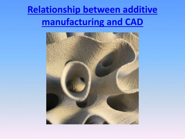
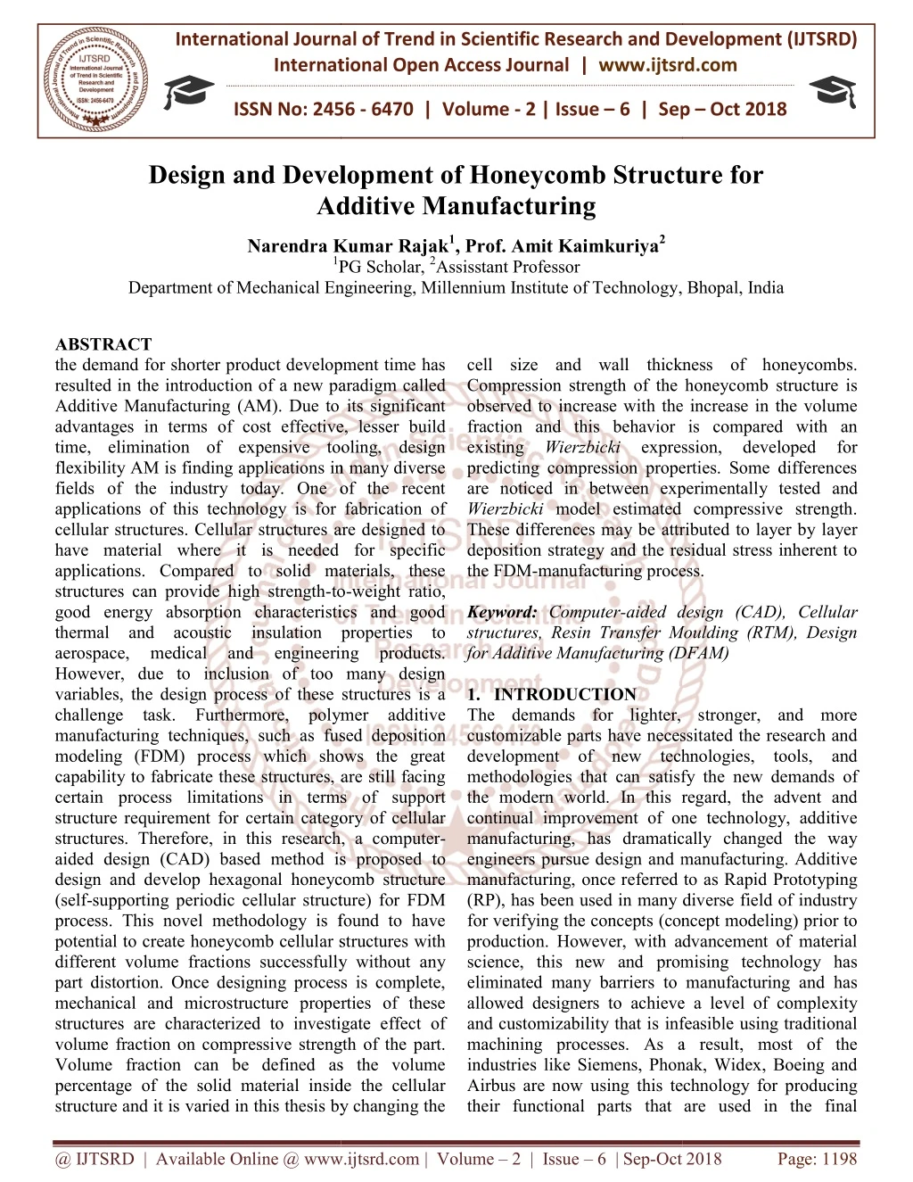
the demand for shorter product development time has resulted in the introduction of a new paradigm called Additive Manufacturing AM . Due to its significant advantages in terms of cost effective, lesser build time, elimination of expensive tooling, design flexibility AM is finding applications in many diverse fields of the industry today. One of the recent applications of this technology is for fabrication of cellular structures. Cellular structures are designed to have material where it is needed for specific applications. Compared to solid materials, these structures can provide high strength to weight ratio, good energy absorption characteristics and good thermal and acoustic insulation properties to aerospace, medical and engineering products. However, due to inclusion of too many design variables, the design process of these structures is a challenge task. Furthermore, polymer additive manufacturing techniques, such as fused deposition modeling FDM process which shows the great capability to fabricate these structures, are still facing certain process limitations in terms of support structure requirement for certain category of cellular structures. Therefore, in this research, a computer aided design CAD based method is proposed to design and develop hexagonal honeycomb structure self supporting periodic cellular structure for FDM process. This novel methodology is found to have potential to create honeycomb cellular structures with different volume fractions successfully without any part distortion. Once designing process is complete, mechanical and microstructure properties of these structures are characterized to investigate effect of volume fraction on compressive strength of the part. Volume fraction can be defined as the volume percentage of the solid material inside the cellular structure and it is varied in this thesis by changing the cell size and wall thickness of honeycombs. Compression strength of the honeycomb structure is observed to increase with the increase in the volume fraction and this behavior is compared with an existing Wierzbicki expression, developed for predicting compression properties. Some differences are noticed in between experimentally tested and Wierzbicki model estimated compressive strength. These differences may be attributed to layer by layer deposition strategy and the residual stress inherent to the FDM manufacturing process. Narendra Kumar Rajak | Prof. Amit Kaimkuriya "Design and Development of Honeycomb Structure for Additive Manufacturing" Published in International Journal of Trend in Scientific Research and Development (ijtsrd), ISSN: 2456-6470, Volume-2 | Issue-6 , October 2018, URL: https://www.ijtsrd.com/papers/ijtsrd18856.pdf Paper URL: http://www.ijtsrd.com/engineering/mechanical-engineering/18856/design-and-development-of-honeycomb-structure-for-additive-manufacturing/narendra-kumar-rajak<br>

E N D
International Journal of Trend in International Open Access Journal International Open Access Journal | www.ijtsrd.com International Journal of Trend in Scientific Research and Development (IJTSRD) Research and Development (IJTSRD) www.ijtsrd.com ISSN No: 2456 ISSN No: 2456 - 6470 | Volume - 2 | Issue – 6 | Sep 6 | Sep – Oct 2018 Design and Develop Design and Development of Honeycomb Structure for Additive Manufacturing ment of Honeycomb Structure for Additive Manufacturing Narendra Kumar Rajak1, Prof. Amit Kaimkuriya2 Narendra Kumar Rajak 1PG Scholar, PG Scholar, 2Assisstant Professor Department of Mechanical Engineering, Millennium Institute of Technology, Bhopal, India Department of Mechanical Engineering , Bhopal, India cell size and wall thickness of honeycombs. Compression strength of the h observed to increase with the increase in the volume fraction and this behavior is compared with an existing Wierzbicki expression, developed for predicting compression properties. Some differences are noticed in between experimentall Wierzbicki model estimated compressive strength. These differences may be attributed to layer by layer deposition strategy and the residual stress inherent to the FDM-manufacturing process. Keyword: Computer-aided design (CAD), Cellular structures, Resin Transfer Moulding (RTM), Design for Additive Manufacturing (DFAM) 1.INTRODUCTION The demands for lighter, stronger, and more customizable parts have necessitated the research and development of new technologies, tools, and methodologies that can satisfy the new demands of the modern world. In this regard, the advent and continual improvement of one technology, additive manufacturing, has dramatically changed the way engineers pursue design and manufacturing. Additive manufacturing, once referred to as Rapid Prototyping (RP), has been used in many diverse field of industry for verifying the concepts (concept modeling) prior to production. However, with advancement of material science, this new and promising technology has eliminated many barriers to manufacturing and has allowed designers to achieve a level of complexity and customizability that is infeasible using traditional machining processes. As a result, most of the industries like Siemens, Phonak, Widex, Boeing and Airbus are now using this technology for producing their functional parts that are used in the final their functional parts that are used in the final ABSTRACT the demand for shorter product development time has resulted in the introduction of a new paradigm called Additive Manufacturing (AM). Due to its significant advantages in terms of cost effective, lesser build time, elimination of expensive tooling, design flexibility AM is finding applications in many diverse fields of the industry today. One of the recent applications of this technology is for fabrication of cellular structures. Cellular structures are designed to have material where it is needed for specific applications. Compared to solid materials, these structures can provide high strength-to good energy absorption characteristics and good thermal and acoustic insulation properties to aerospace, medical and However, due to inclusion of too many design variables, the design process of these structures is a challenge task. Furthermore, polymer additive manufacturing techniques, such as fused deposition modeling (FDM) process which shows the great capability to fabricate these structures, are still facing certain process limitations in terms of support structure requirement for certain category of cellular structures. Therefore, in this research, a computer aided design (CAD) based method is proposed to design and develop hexagonal honeycomb structure (self-supporting periodic cellular structure) for FDM process. This novel methodology is found to have potential to create honeycomb cellular structures with different volume fractions successfully without any part distortion. Once designing process is complete, mechanical and microstructure properties of these structures are characterized to investigate effect of volume fraction on compressive strength of the part. Volume fraction can be defined as the volume percentage of the solid material inside the cellular structure and it is varied in this thesis by changing the structure and it is varied in this thesis by changing the the demand for shorter product development time has resulted in the introduction of a new paradigm called Additive Manufacturing (AM). Due to its significant n terms of cost effective, lesser build time, elimination of expensive tooling, design flexibility AM is finding applications in many diverse fields of the industry today. One of the recent applications of this technology is for fabrication of uctures. Cellular structures are designed to have material where it is needed for specific applications. Compared to solid materials, these cell size and wall thickness of honeycombs. Compression strength of the honeycomb structure is observed to increase with the increase in the volume fraction and this behavior is compared with an expression, predicting compression properties. Some differences are noticed in between experimentally tested and model estimated compressive strength. These differences may be attributed to layer by layer deposition strategy and the residual stress inherent to manufacturing process. developed for to-weight ratio, good energy absorption characteristics and good oustic insulation properties to aerospace, medical and However, due to inclusion of too many design variables, the design process of these structures is a challenge task. Furthermore, polymer additive aided design (CAD), Cellular structures, Resin Transfer Moulding (RTM), Design for Additive Manufacturing (DFAM) engineering engineering products. products. The demands for lighter, stronger, and more customizable parts have necessitated the research and development of new technologies, tools, and at can satisfy the new demands of the modern world. In this regard, the advent and continual improvement of one technology, additive manufacturing, has dramatically changed the way engineers pursue design and manufacturing. Additive erred to as Rapid Prototyping (RP), has been used in many diverse field of industry for verifying the concepts (concept modeling) prior to production. However, with advancement of material science, this new and promising technology has iers to manufacturing and has allowed designers to achieve a level of complexity and customizability that is infeasible using traditional machining processes. As a result, most of the industries like Siemens, Phonak, Widex, Boeing and this technology for producing fused deposition modeling (FDM) process which shows the great capability to fabricate these structures, are still facing certain process limitations in terms of support structure requirement for certain category of cellular research, a computer- aided design (CAD) based method is proposed to design and develop hexagonal honeycomb structure supporting periodic cellular structure) for FDM process. This novel methodology is found to have ar structures with different volume fractions successfully without any part distortion. Once designing process is complete, mechanical and microstructure properties of these structures are characterized to investigate effect of ve strength of the part. Volume fraction can be defined as the volume percentage of the solid material inside the cellular @ IJTSRD | Available Online @ www.ijtsrd.com www.ijtsrd.com | Volume – 2 | Issue – 6 | Sep-Oct 2018 Oct 2018 Page: 1198
International Journal of Trend in Scientific Research and Development (IJTSR International Journal of Trend in Scientific Research and Development (IJTSRD) ISSN: 2456 D) ISSN: 2456-6470 products. One such application of this technology is for manufacturing of customized, lightweight cellular structures. They have several advantages such as high strength-to-weight ratio and strong thermal and acoustic insulation properties. These types of structures are suitable for any weight applications, particularly in the aerospace and automotive industries. This research will present a method for the design of these cellular structures for mold making application. Additive manufacturing (AM) is an additive fabrication process where a three-dimensional part is produced by stacking layers of thin 2 sectional slices of materials one over another use of tooling and human intervention. The process begins with a solid model CAD drawing of the object. The CAD model is then converted in to .STL file format and sent to an AM machine for prototype building [1]. The whole process of design to phy model through various intermediate interfacing stages is shown in Fig. 1. These steps are common to most AM systems but the mechanisms by which the individual layers are created depend on the specific system. Currently, many technologies exist that definition of AM. These technologies are supported by various distinct process categories. These are: photo polymerization, powder bed fusion, extrusion based systems, printing, sheet lamination, beam deposition, and direct write technologie of these processes has its own distinct set of advantages and disadvantages characteristics such as surface finish, manufacturing speed and layer resolution. Of these different processes, three technologies are most commonly used: fused deposition modeling (FDM), stereo lithography (SLA) and selective laser sintering (SLS). These three processes will be briefly outlined in the following sections. products. One such application of this technology is for manufacturing of customized, lightweight cellular structures. They have several advantages such as high ght ratio and strong thermal and acoustic insulation properties. These types of structures are suitable for any weight-critical applications, particularly in the aerospace and automotive industries. This research will present a Fused Deposition Modelling (FDM) was introduced and commercialized by Stratasys, Minnesota, USA in 1991.FDM process builds prototype by extruding material (normally thermoplastic like ABS) through a nozzle that traverses in X and Y to create each two dimensional layer. As each layer is extruded, it bonds to the previous layer and solidify. The platform is then lowered relative to the nozzle and the next slice of the part is deposited on top of the previous slice. A second nozzle is used to extrude a different material up support structures for the part Fused Deposition Modelling (FDM) was intr and commercialized by Stratasys, Minnesota, USA in 1991.FDM process builds prototype by extruding material (normally thermoplastic like ABS) through a nozzle that traverses in X and Y to create each two dimensional layer. As each layer is extruded, to the previous layer and solidify. The platform is then lowered relative to the nozzle and the next slice of the part is deposited on top of the previous slice. A second nozzle is used to extrude a different material in order to build-up support where needed. 2.LITERATURE SURVEY Yu and Li et al.[1991] This paper proposes to use solid offset to cut down the solid volume to be built. The background theory for obtaining the reduced volume solid is negatively offsetting the CSG approach is applicable to solids defined by constructive solid geometry (CSG) Ganesan and Fadelet al [1993] method is presented here for creating (outside of the solid modeler) hollow CAD models of the object using offsetting techniques. This method is not suitable for creating hollow parts that have varying surface normals. Koc and Leeet al. [1993] This paper presents a new method of using non-uniform offsetting and biarcs fitting to hollow out solid objects or thick walls speed up the part building processes on rapid prototyping (RP) systems. Offset STL model contains some triangular facets with overlaps and inconsistent orientations. Qu and stuckeret al[1994] new 3D offset method for modifying C in the STL format. In this method, vertices, instead of facets, are offset. The magnitude and direction of each vertex offset is calculated using the weighted sum of the normals of the facets that are connected to each vertex. Liu and Chenet al.[1996] demands of hollowed prototypes in casting and rapid prototype manufacturing. Offsetting along the Z and cross sectional contour offsetting are employed to perform the hollowing operation. Dutra et alet al.[1998] measured the stiffness of Ti 6Al–4V open cellular foams fabricated by electron 4V open cellular foams fabricated by electron se cellular structures for Additive manufacturing (AM) is an additive dimensional part is produced by stacking layers of thin 2-D cross sectional slices of materials one over another without use of tooling and human intervention. The process begins with a solid model CAD drawing of the object. The CAD model is then converted in to .STL file format and sent to an AM machine for prototype building [1]. The whole process of design to physical model through various intermediate interfacing stages is shown in Fig. 1. These steps are common to most AM systems but the mechanisms by which the individual layers are created depend on the specific LITERATURE SURVEY This paper proposes to use solid offset to cut down the solid volume to be built. The background theory for obtaining the reduced- volume solid is negatively offsetting the CSG The approach is applicable to solids defined by constructive solid geometry (CSG) 1993] A simple effective method is presented here for creating (outside of the solid modeler) hollow CAD models of the object techniques. This method is not suitable for creating hollow parts that have varying Currently, many technologies exist that into the broad definition of AM. These technologies are supported by various distinct process categories. These are: photo polymerization, powder bed fusion, extrusion- based systems, printing, sheet lamination, beam deposition, and direct write technologies [2, 3]. Each of these processes has its own distinct set of advantages and disadvantages characteristics such as surface finish, manufacturing speed and layer resolution. Of these different processes, three technologies are most commonly fused deposition modeling (FDM), stereo lithography (SLA) and selective laser sintering (SLS). These three processes will be briefly outlined in the This paper presents a new uniform offsetting and biarcs fitting to hollow out solid objects or thick walls to speed up the part building processes on rapid prototyping (RP) systems. Offset STL model contains some triangular facets with overlaps and inconsistent regarding regarding [1994] This paper presents a new 3D offset method for modifying CAD model data in the STL format. In this method, vertices, instead of facets, are offset. The magnitude and direction of each vertex offset is calculated using the weighted sum of the normals of the facets that are connected to each t al.[1996] presented to meet the demands of hollowed prototypes in casting and rapid prototype manufacturing. Offsetting along the Z-axis and cross sectional contour offsetting are employed to perform the hollowing operation. sured the stiffness of Ti– Figure 1: CAD-Prototype intermediate stages Prototype intermediate stages @ IJTSRD | Available Online @ www.ijtsrd.com www.ijtsrd.com | Volume – 2 | Issue – 6 | Sep-Oct 2018 Oct 2018 Page: 1199
International Journal of Trend in Scientific Research and Development (IJTSR International Journal of Trend in Scientific Research and Development (IJTSRD) ISSN: 2456 D) ISSN: 2456-6470 beam melting (EBM). Results are found to be in good agreement with the Gibson–Ashby model for open cellular foam materials Wang and McDowell have performed a comprehensive review o modeling, mechanics, and characteristics of various metal honeycombs. Garcia et al [1999] CNTs were grown on alumina fiber cloth. These fibers were used as reinforcements in matrix material. The growth of CNTs led to an increase in inter-laminar shear properties of the order of 69% as compared to alumina cloth composite the elastic properties of FFRC (Fuzzy fiber reinforced composite) using mechanics of materials approach and Mori-Tanaka method considering with and without the interphase between CNT and polymer. Johnson et al. [2000] comprehensive analytical model of the truss structure by considering each strut as a beam experiencing axial, bending, shearing, and torsion effects. He analyzed the octet-truss structure inside fi environment using a unit-truss model that consists of a node and set of half-struts connecting to the node. Chang et. al.[2005] A standard thermosetting liquid resin, with the commercial brand name Quires 406 PA is used in the matrix in the form of orthophthalic unsaturated polyester (UP). It is acquired from the company MR-Dinis dos Santos (Lisbon, Portugal) and its characteristics are presented in the APPENDIX B. Neshumayevet. al.[2006] RTM processes are capable to manufacture high geomet parts and due to the comparably low cost of the raw materials and preforming technologies, it is applicable for medium size manufacturing series. However, for successful composite fabrication in RTM process, proper mold design should be done processing. Moreover when mold is in complex in nature. 3.PROBLEM IDENTIFICATION RESEARCH OBJECTIVE The basic problem definition is as follows Design of cellular solid is often a difficult task using existing CAD packages due to the level of complexity associated with it. Designed by FDM is tested for RTM application. The complete process should be integrated with the existing CAD platform beam melting (EBM). Results are found to be in good The main research objectives is as follows Generate and design periodic cellular structures e.g. honeycomb shaped Whole program is automated using VB script programming and is validated for many complex shaped parts. 4.METHODOLOGY In order to understand optimization of structures, the definitions of three categories optimization are explained below. Literature reveals that the optimization of part geometry and topology of the structural lay-out has a great impact on the performance of the structures. main research objectives is as follows Generate and design periodic cellular structures Ashby model for open cellular foam materials Wang and McDowell have performed a comprehensive review of analytical modeling, mechanics, and characteristics of various Whole program is automated using VB script programming and is validated for many complex CNTs were grown on alumina fiber cloth. These fibers were used as reinforcements in matrix material. The growth of CNTs led to an nar shear properties of the order of 69% as compared to alumina cloth composite the elastic properties of FFRC (Fuzzy fiber reinforced composite) using mechanics of materials approach Tanaka method considering with and mization of structures, the categories definitions optimization are explained below. Literature reveals that the optimization of part geometry and topology of out has a great impact on the of three of of structural structural en CNT and polymer. ] provided provided a a more more comprehensive analytical model of the truss structure by considering each strut as a beam experiencing axial, bending, shearing, and torsion effects. He truss structure inside finite-element truss model that consists of struts connecting to the node. Figure 2: Size (top), shape (middle) and topology (bottom) optimization A typical size optimization involves finding the optimal cross-sectional area of each strut in a truss structure. Shape optimization computes the optimal form that defined by the boundary curves or boundary surfaces of the body. The process may involve moving nodes to change the shape of the structure; however, the element-node connectivity remains intact. According to Rozvany, topology optimization can be defined as determining the optimal connective sequences of members or elements in a structure. It consists of both size and shape optimization and has been used most frequently by design engineers to optimize their part structures for AM application. The topology optimization techniques used by the design are based on one of two approaches: the homogenization (continuum) approach and the ground (discrete) truss approach. By using some continuous variables such as cross-sectional area, void sizes, these two approaches transfor into a continuous one. The details of these two approaches are discussed in. Though structural optimization approach is used for the design, there is always a need for actual optimization routine. There are many different optimization algorithms depending on the applications such as mathematical programming techniques, such as mathematical programming techniques, Figure 2: Size (top), shape (middle) and topology (bottom) optimization A typical size optimization involves finding the sectional area of each strut in a truss structure. Shape optimization computes the optimal the boundary curves or boundary surfaces of the body. The process may involve moving nodes to change the shape of the structure; node connectivity remains intact. According to Rozvany, topology optimization A standard thermosetting liquid resin, with the commercial brand name Quires 406 PA form of orthophthalic unsaturated polyester (UP). It is acquired from the Dinis dos Santos (Lisbon, Portugal) and its characteristics are presented in the APPENDIX B. RTM processes are ng the optimal connective capable to manufacture high geometrical complex parts and due to the comparably low cost of the raw materials and preforming technologies, it is applicable for medium size manufacturing series. However, for successful composite fabrication in RTM process, proper mold design should be done prior to processing. Moreover when mold is in complex in sequences of members or elements in a structure. It consists of both size and shape optimization and has been used most frequently by design engineers to optimize their part structures for AM application. n techniques used by the design are based on one of two approaches: the homogenization (continuum) approach and the ground (discrete) truss approach. By using some continuous sectional area, void sizes, these two approaches transform the discrete problem into a continuous one. The details of these two PROBLEM IDENTIFICATION & & The basic problem definition is as follows Design of cellular solid is often a difficult task using existing CAD packages due to the level of Though structural optimization approach is used for the design, there is always a need for actual optimization routine. There are many different optimization algorithms depending on the applications Designed by FDM is tested for RTM application. The complete process should be integrated with @ IJTSRD | Available Online @ www.ijtsrd.com www.ijtsrd.com | Volume – 2 | Issue – 6 | Sep-Oct 2018 Oct 2018 Page: 1200
International Journal of Trend in Scientific Research and Development (IJTSR International Journal of Trend in Scientific Research and Development (IJTSRD) ISSN: 2456 D) ISSN: 2456-6470 stochastic process techniques, and statistical methods. According to Rozvany and Zhou, these algorithms fall in two categories: direct methods and indirect method. Direct methods (mathematical programming) consist of iteratively calculating the value of the objective function, its gradient with respect to all the design variables, and a change of design variables resulting in cost reduction until the local minimum of the objective function is found. These methods are very robust, however, the calculation of gradients c time-taking process, and sometimes can only optimize a limited number of design variables. On the other hand, indirect methods, such as optimality criterion, attempt to satisfy some design criteria of the structure instead of optimizing the main objective function. In many cases, such as uniform stresses, it has been found that direct method provides the same solutions as that of indirect methods. Chu et al. compared the performance of three methods namely, Particle Swam Levenberg-Marquardt (LM) Marquardt (LM) rocess techniques, and statistical methods. According to Rozvany and Zhou, these algorithms fall in two categories: direct methods and indirect method. Direct methods (mathematical programming) consist of iteratively calculating the value of the objective function, its gradient with respect to all the design variables, and a change of design variables resulting in cost reduction until the local minimum of the objective function is found. These methods are very robust, however, the calculation of gradients can be taking process, and sometimes can only optimize Programming while designing octet lattice cellular structures to achieve desired strength and stiffness. Results show that LM is more efficient algorithms for Programming while designing octet lattice cellular structures to achieve desired strength and stiffness. Results show that LM is more efficient algorithms for this class of problems. Selection of an appropriate process requi addressing to various criteria such as cost, part quality, part properties, build envelope, build time (speed) and other concerns suiting to a particular situation. A number of studies have been carried out in this direction, predominantly concerning w development of decision support systems for assisting AM users in selecting the most appropriate AM process. 5.RESULT AND ANALYSIS In this section, a comparative benchmarking analysis between three infill patterns of the mould such as solid, sparse and honeycomb is presented. It will be interesting to know their material count and build time. Table 1 shows these values along with their respective build times and weights. Selection of an appropriate process requires addressing to various criteria such as cost, part quality, part properties, build envelope, build time (speed) and other concerns suiting to a particular situation. A number of studies have been carried out in this direction, predominantly concerning with the development of decision support systems for assisting AM users in selecting the most appropriate AM On the other hand, indirect methods, such as optimality criterion, attempt to satisfy some design criteria of the structure instead of optimizing the main jective function. In many cases, such as uniform stresses, it has been found that direct method provides the same solutions as that of indirect methods. Chu et al. compared the performance of three methods namely, Particle Swam RESULT AND ANALYSIS In this section, a comparative benchmarking analysis between three infill patterns of the mould such as and honeycomb is presented. It will be interesting to know their material count and build time. Table 1 shows these values along with their respective build times and weights. Optimization and and Optimization (PSO), Active Active-set (PSO), Table 1: RTM mould characterization with three different infill patterns Infill PatternRTM mouldModel Bottom Top Total Bottom Top Total Bottom Top Total 182.71 Table 1: RTM mould characterization with three different infill patterns Table 1: RTM mould characterization with three different infill patterns Model Material (cc3)Build Time (hr : min) 169.66 166.77 336.43 53.96 50.71 104.67 111.59 71.12 Weight (gram) 7.42 7.29 14.71 3.52 4.05 7.57 13.25 11.44 24.69 Solid 333 Sparse 102 Honeycomb 228 Figure 3: Trade Figure 3: Trade-off between build time and infill pattern @ IJTSRD | Available Online @ www.ijtsrd.com www.ijtsrd.com | Volume – 2 | Issue – 6 | Sep-Oct 2018 Oct 2018 Page: 1201
International Journal of Trend in Scientific Research and Development (IJTSRD) ISSN: 2456 International Journal of Trend in Scientific Research and Development (IJTSRD) ISSN: 2456 International Journal of Trend in Scientific Research and Development (IJTSRD) ISSN: 2456-6470 From the above table, it is clear that solid mould is consuming more material followed by honeycomb and sparse. The time taken to print these moulds also found to be in the same order as of material. It is also noted that though material and build time is minimum for sparse mould it failed during testing due to insufficient resistance to the applied force, whereas honeycomb mould is able to resist the load without any deformation. In this regard, direct 30% weight reduction is achieved which in turn will reduce the mould fabrication cost. For a clear understanding, bar graphs are also presented displaying the material consumption and build time consumed by these moulds. 6.CONCLUSIONS AND FUTURE WORK FDM is a promising technology that builds part of any geometry by sequential deposition of the material extruded out from the tip of a nozzle in a temperature controlled environment. It has significant adva in terms of elimination of expensive tooling, flexibility, and possibility of producing complex parts and shapes. One of the current challenges faced by FDM users relates to the cost of prototype and this is partly attributed to expensive process-ab this direction the present work emphasizes on the improving material distribution by introducing cellular solids since they offer significantly high strength at low relative mass. DFM is a useful approach to reduce, and hopefully minimize, manufacturing and assembly difficulties and costs. This engineering technique focuses not only on the design of a part but also on its producibility. The ease of producing a part with a manufacturing process can dramatically reduce its manufacturing costs. Producibility is not only affected by the manufacturing process but also by the geometry of the part, and many other properties of the part. To take advantage of this approach, it is necessary to identify their (additive manufacturing processes) specific manufacturing capabilities as well as their manufacturing constraints that must be respected. The need for minimizing the expensive build materials, fabrication time, energy consumption motivated the researchers towards designing cellular structures since a key advantage offered by these structure is high strength accompanied by a relatively low mass. However due to their complexity it is often difficult to generate using conventional manufacturing difficult to generate using conventional manufacturing From the above table, it is clear that solid mould is consuming more material followed by honeycomb and sparse. The time taken to print these moulds is also found to be in the same order as of material. It is also noted that though material and build time is minimum for sparse mould it failed during testing due to insufficient resistance to the applied force, whereas process. In this regard, advances in AM and CAD have allowed for the creation of From mechanical characterization analysis, it is found that compressive strength of honeycomb is independent of height and cell size rather dependent upon their relative density. Relative density or volume fraction is ned as the volume percentage of the solid material process. In this regard, advances in AM and CAD systems have allowed for the creation of mechanical characterization analysis, it is found that compressive strength of honeycomb is independent of height and cell size rather dependent upon their relative density. Relative density or volume fraction is defined as the volume percentage of the solid material in the cellular structure. It can be varied by controlling cell size and wall thickness. An increase in wall thickness and decrease in cell size, results increase in part density as well as relative density. It is also noticed that compressive strength of the cellular structure also increases with increase in relative density. This increasing trend is later confirmed with Gibson-Ashby model with some deviation in the plot. The deviation may be attribu to the residual stress and layer by layer deposition strategy of AM process. In this research, only hexagonal honeycomb, designed by FDM is tested for RTM application. In future, other category of cellular structure such as truss structure should be investigated to study their properties. Though honeycomb cellular structure is designed, it’s optimization is not carried out yet for the given loading condition. It should be taken in to consideration for generating optimal part design. Tool-path optimization should be in future in order to reduce build time of the honeycomb structure which will enable low cost FDM products. In addition, the complete process should be integrated with the existing CAD platform, installation, for quick and an easy part generation. 7. References 1.S. Upcraft and R. Fletcher, “The Rapid Prototyping Technologies,” Automation, vol. 23(4), pp. 318 , vol. 23(4), pp. 318-330, 2003 he load without any deformation. In this regard, direct 30% weight reduction is achieved which in turn will reduce the mould fabrication cost. For a clear understanding, bar graphs are also presented displaying the material It can be varied by controlling cell size and wall thickness. An increase in wall thickness and decrease in cell size, results increase in part density as well as density. It is also noticed that compressive strength of the cellular structure also increases with increase in relative density. This increasing trend is med by these Ashby model with some CONCLUSIONS AND FUTURE WORK FDM is a promising technology that builds part of any geometry by sequential deposition of the material extruded out from the tip of a nozzle in a temperature controlled environment. It has significant advantages in terms of elimination of expensive tooling, flexibility, and possibility of producing complex parts and shapes. One of the current challenges faced by FDM users relates to the cost of prototype and this is deviation in the plot. The deviation may be attributed to the residual stress and layer by layer deposition In this research, only hexagonal honeycomb, designed by FDM is tested for RTM application. In future, other category of cellular structure such as truss nvestigated to study their properties. Though honeycomb cellular structure is designed, it’s optimization is not carried out yet for the given loading condition. It should be taken in to consideration for generating optimal part design. ion should be in future in order to reduce build time of the honeycomb structure which will enable low cost FDM products. In addition, the complete process should be integrated with the existing CAD platform, able material. In this direction the present work emphasizes on the improving material distribution by introducing cellular solids since they offer significantly high DFM is a useful approach to reduce, and hopefully , manufacturing and assembly difficulties and costs. This engineering technique focuses not only on the design of a part but also on its producibility. The ease of producing a part with a manufacturing process can dramatically reduce its s. Producibility is not only affected by the manufacturing process but also by the geometry of the part, and many other properties of the part. To take advantage of this approach, it is necessary to identify their (additive manufacturing c manufacturing capabilities as well as their manufacturing constraints that must be through through n easy part generation. an an add add-on S. Upcraft and R. Fletcher, “The Rapid Prototyping Technologies,” Assembly 2.C. C. Kai and L. K Fai, “Rapid Prototyping: Principles and Applications in Manufacturing,” John Wiley and Sons, Singapore, 1997 , Singapore, 1997 C. C. Kai and L. K Fai, “Rapid Prototyping: Principles and Applications in Manufacturing,” 3.S.S. Mahapatra and B. N. Panda, "Benchmarking of rapid prototyping systems using grey relational analysis," Int. J. Services and Operations Management, Vol. 16, No. 4, pp.460 , Vol. 16, No. 4, pp.460–477, 2013 S.S. Mahapatra and B. N. Panda, "Benchmarking of rapid prototyping systems using grey relational Int. J. Services and Operations The need for minimizing the expensive build materials, fabrication time, energy consumption motivated the researchers towards designing cellular nce a key advantage offered by these structure is high strength accompanied by a relatively low mass. However due to their complexity it is often 4.R. Noorani, “Rapid Prototyping Application,” John Wiley & Sons USA, 2005 R. Noorani, “Rapid Prototyping-Principles and John Wiley & Sons, New Jersey, 5.S. H. Masood and W. Q. Song, “Development of New Metal / Polymer Materials for Rapid Tooling New Metal / Polymer Materials for Rapid Tooling S. H. Masood and W. Q. Song, “Development of @ IJTSRD | Available Online @ www.ijtsrd.com www.ijtsrd.com | Volume – 2 | Issue – 6 | Sep-Oct 2018 Oct 2018 Page: 1202
International Journal of Trend in Scientific Research and Development (IJTSR International Journal of Trend in Scientific Research and Development (IJTSRD) ISSN: 2456 D) ISSN: 2456-6470 22.M. F. Ashby, A. G. Evans, N. A. Fleck, L. J. Gibson, J. W. Hutchinson, and H. N. G. Wadley, Metals Foams: A Design Guide Butterworth-Heinemann, 2000. Heinemann, 2000. using Fused Deposition Modelling,” Design, vol. 25, pp. 587-594, 2004. using Fused Deposition Modelling,” Materials & A. G. Evans, N. A. Fleck, L. J. Gibson, J. W. Hutchinson, and H. N. G. Wadley, Metals Foams: A Design Guide. Woburn, MA: 6."Image: http://chuansong.me/n/492448 FDM Process ocess Flow," Flow," ed. ed. 23.J. Chu, S. Engelbrecht, G. Graf, and D. W. Rosen, "A comparison of synthesis methods for cellular structures with application manufacturing," Rapid Prototyping Journal, 16, pp. 275-283, 2010. J. Chu, S. Engelbrecht, G. Graf, and D. W. Rosen, "A comparison of synthesis methods for cellular ures with application Rapid Prototyping Journal, vol. 7. http://www.stratasys.com/industries/automotive http://www.stratasys.com/industries/automotive 8.P. P. Manufacturing: F. F. Jabobs, Jabobs, "Rapid Fundamentals Fundamentals "Rapid Prototyping of of Hill, 1993. Prototyping & & to to additive additive Manufacturing: lithography," TX: McGraw-Hill, 1993. Stereo 9."Image: http://www.medical.siemens.com. "Image: Siemens Siemens hearing hearing aid," aid," ed. ed. 24.K.M. Yu and C.L. Li, "Speeding up rapid prototyping by offset, Proceedings of the Institute of Mechanical Engineers," Engineering Manufacturing 1995. K.M. Yu and C.L. Li, "Speeding up rapid prototyping by offset, Proceedings of the Institute of Mechanical Engineers," Part B: Journal of anufacturing, Vol. 209, pp.1-8, 10."Image: http://www.invisalign.com. "Image: Invisalign Invisalign braces," braces," ed. ed. 11.D. W. Rosen, I. Gibson, and B. Stucker, "Additive Manufacturing Technologies," Springer D. W. Rosen, I. Gibson, and B. Stucker, "Additive 25.M. Ganesan, and G. M Fadel, “Hollowing rapid prototyping parts using offsetting techniques,” Proceedings of the 5th International Conference on Rapid Prototyping, June 1994, University of Dayton Research Institute, Da Dayton Research Institute, Dayton, 1994. M. Ganesan, and G. M Fadel, “Hollowing rapid prototyping parts using offsetting techniques,” Proceedings of the 5th International Conference , June 1994, University of Springer, 2010. 12.J. Wooten, "Aeronautical case studies using rapid manufacture, in Rapid Manufacturing (Hopkinson, N., Hague, R., and Dickens, P., eds.)," ch. 15, John Wiley & Sons, 2006 dies using rapid manufacture, in Rapid Manufacturing (Hopkinson, N., Hague, R., and Dickens, P., eds.)," ch. 15, 26.[26] B. Koc, and Y. S. Lee, "Non offsetting and hollowing objects by using biarcs fitting for rapid Computers in Industry, Vol. 47, pp. 1 Computers in Industry, Vol. 47, pp. 1-23, 2002. [26] B. Koc, and Y. S. Lee, "Non-uniform offsetting and hollowing objects by using biarcs fitting for rapid 13."Image: http://www.steg.com.au/capabilities/additive manufacturing/metals/ "Image: http://www.steg.com.au/capabilities/additive Propellor," Propellor," Ed. prototyping prototyping processes," processes," 14.Vayre, Benjamin, F. Vignat, and F. Villeneuve, "Identification on some design key parameters for additive manufacturing: application on Electron Beam Melting," Procedia CIRP, Vol.7, pp.264 269, 2013. and F. Villeneuve, 27.[27]X. Qu and B, Stucker, "A 3D surface offset method for STL-format Prototyping Journal, Vol.9 (3), pp.133 Prototyping Journal, Vol.9 (3), pp.133-141, 2003. [27]X. Qu and B, Stucker, "A 3D surface offset format "Identification on some design key parameters for additive manufacturing: application on Electron models," models," Rapid Rapid Vol.7, pp.264- 28.Park, and C. Sang, Hollowing objects with uniform wall thickness," Computer Vol.37, pp.451–460, 2005 Park, and C. Sang, Hollowing objects with uniform wall thickness," Computer-Aided Design, 15. www.amrc.co.uk/wp- content/uploads/AMRC_DPG_CircuitBracket.pdf content/uploads/AMRC_DPG_CircuitBracket.pdf 29.Z. Zhengyu, D. Yucheng and H. Jun, A new hollowing process for ra Rapid Prototyping Journal, Vol. 10(3), pp. 166 175, 2004 Z. Zhengyu, D. Yucheng and H. Jun, A new hollowing process for rapid prototype models," Rapid Prototyping Journal, Vol. 10(3), pp. 166- 16.http://www.eos.info/eos_airbusgroupinnovationtea m_aerospace_sustainability study o/eos_airbusgroupinnovationtea 17.http://www.geaviation.com/company/additive manufacturing.html http://www.geaviation.com/company/additive- 30.L. E. Murr, et al. "Characterization of Ti open cellular foams fabricated by additive manufacturing using electron beam melting." Materials Science and Engineering: Vol. A 527.7, pp.1861-1868, 2010 et al. "Characterization of Ti–6Al–4V open cellular foams fabricated by additive manufacturing using electron beam melting." Materials Science and Engineering: Vol. A 527.7, 18.Yan, Chunze, et al. "Evaluations of cellular lattice structures manufactured using selective laser melting." International Journal of Machine Tools and Manufacture, vol.62,pp. 32-38, 2012. Yan, Chunze, et al. "Evaluations of cellular lattice structures manufactured using selective laser of Machine Tools 38, 2012. 19."Image: http://www.ec21.com/offer_detail/Sell_SSH 301_and_SSH- 304_Stainless--2359 "Image: http://www.ec21.com/offer_detail/Sell_SSH- Honeycomb," Honeycomb," ed. ed. 23593211.html. 20."Image: http://www.zhongweiaf.com/en/ "Image: Foam," Foam," ed. ed. 21.V. S. Deshpande, N. A. Fleck, and M. F. Ashby, "Effective properties of the octet material," Journal of Mechanics and Physics of Solids, vol. 49, pp. 1747-1769, 2001 V. S. Deshpande, N. A. Fleck, and M. F. Ashby, "Effective properties of the octet-truss lattice Journal of Mechanics and Physics of 1769, 2001 @ IJTSRD | Available Online @ www.ijtsrd.com www.ijtsrd.com | Volume – 2 | Issue – 6 | Sep-Oct 2018 Oct 2018 Page: 1203