Download
1 / 5
50 likes | 54 Vues
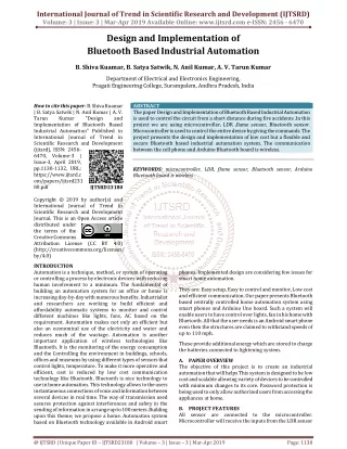
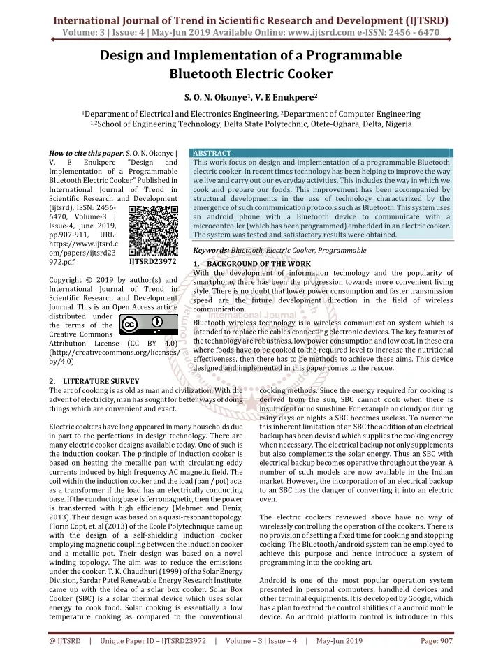
This work focus on design and implementation of a programmable Bluetooth electric cooker. In recent times technology has been helping to improve the way we live and carry out our everyday activities. This includes the way in which we cook and prepare our foods. This improvement has been accompanied by structural developments in the use of technology characterized by the emergence of such communication protocols such as Bluetooth. This system uses an android phone with a Bluetooth device to communicate with a microcontroller which has been programmed embedded in an electric cooker. The system was tested and satisfactory results were obtained. S. O. N. Okonye | V. E Enukpere "Design and Implementation of a Programmable Bluetooth Electric Cooker" Published in International Journal of Trend in Scientific Research and Development (ijtsrd), ISSN: 2456-6470, Volume-3 | Issue-4 , June 2019, URL: https://www.ijtsrd.com/papers/ijtsrd23972.pdf Paper URL: https://www.ijtsrd.com/engineering/electronics-and-communication-engineering/23972/design-and-implementation-of-a-programmable-bluetooth-electric-cooker/s-o-n-okonye<br>

E N D
International Journal of Trend in Scientific Research and Development (IJTSRD) Volume: 3 | Issue: 4 | May-Jun 2019 Available Online: www.ijtsrd.com e-ISSN: 2456 - 6470 Design and Implementation of a Programmable Bluetooth Electric Cooker S. O. N. Okonye1, V. E Enukpere2 1Department of Electrical and Electronics Engineering, 2Department of Computer Engineering 1,2School of Engineering Technology, Delta State Polytechnic, Otefe-Oghara, Delta, Nigeria How to cite this paper: S. O. N. Okonye | V. E Enukpere Implementation of a Programmable Bluetooth Electric Cooker" Published in International Journal of Trend in Scientific Research and Development (ijtsrd), ISSN: 2456- 6470, Volume-3 | Issue-4, June 2019, pp.907-911, URL: https://www.ijtsrd.c om/papers/ijtsrd23 972.pdf Copyright © 2019 by author(s) and International Journal of Trend in Scientific Research and Development Journal. This is an Open Access article distributed under the terms of the Creative Commons Attribution License (CC BY 4.0) (http://creativecommons.org/licenses/ by/4.0) 2.LITERATURE SURVEY The art of cooking is as old as man and civilization. With the advent of electricity, man has sought for better ways of doing things which are convenient and exact. Electric cookers have long appeared in many households due in part to the perfections in design technology. There are many electric cooker designs available today. One of such is the induction cooker.The principle of induction cooker is based on heating the metallic pan with circulating eddy currents induced by high frequency AC magnetic field. The coil within the induction cooker and the load (pan / pot) acts as a transformer if the load has an electrically conducting base. If the conducting base is ferromagnetic, then the power is transferred with high efficiency (Mehmet and Deniz, 2013). Their design was based on a quasi-resonant topology. Florin Copt, et. al (2013) of the Ecole Polytechnique came up with the design of a self-shielding induction cooker employing magnetic coupling between the induction cooker and a metallic pot. Their design was based on a novel winding topology. The aim was to reduce the emissions under the cooker. T. K. Chaudhuri (1999) of the Solar Energy Division, Sardar Patel Renewable Energy Research Institute, came up with the idea of a solar box cooker. Solar Box Cooker (SBC) is a solar thermal device which uses solar energy to cook food. Solar cooking is essentially a low temperature cooking as compared to the conventional ABSTRACT This work focus on design and implementation of a programmable Bluetooth electric cooker. In recent times technology has been helping to improve the way we live and carry out our everyday activities. This includes the way in which we cook and prepare our foods. This improvement has been accompanied by structural developments in the use of technology characterized by the emergence of such communication protocols such as Bluetooth. This system uses an android phone with a Bluetooth device to communicate with a microcontroller (which has been programmed) embedded in an electric cooker. The system was tested and satisfactory results were obtained. Keywords: Bluetooth, Electric Cooker, Programmable 1.BACKGROUND OF THE WORK With the development of information technology and the popularity of smartphone, there has been the progression towards more convenient living style. There is no doubt that lower power consumption and faster transmission speed are the future development direction in the field of wireless communication. Bluetooth wireless technology is a wireless communication system which is intended to replace the cables connecting electronic devices. The key features of the technology are robustness, low power consumption and low cost. In these era where foods have to be cooked to the required level to increase the nutritional effectiveness, then there has to be methods to achieve these aims. This device designed and implemented in this paper comes to the rescue. cooking methods. Since the energy required for cooking is derived from the sun, SBC cannot cook when there is insufficient or no sunshine. For example on cloudy or during rainy days or nights a SBC becomes useless. To overcome this inherent limitation of an SBC the addition of an electrical backup has been devised which supplies the cooking energy when necessary. The electrical backup not only supplements but also complements the solar energy. Thus an SBC with electrical backup becomes operative throughout the year. A number of such models are now available in the Indian market. However, the incorporation of an electrical backup to an SBC has the danger of converting it into an electric oven. The electric cookers reviewed above have no way of wirelessly controlling the operation of the cookers. There is no provision of setting a fixed time for cooking and stopping cooking. The Bluetooth/android system can be employed to achieve this purpose and hence introduce a system of programming into the cooking art. Android is one of the most popular operation system presented in personal computers, handheld devices and other terminal equipments. It is developed by Google, which has a plan to extend the control abilities of a android mobile device. An android platform control is introduce in this "Design and IJTSRD23972 @ IJTSRD | Unique Paper ID – IJTSRD23972 | Volume – 3 | Issue – 4 | May-Jun 2019 Page: 907
International Journal of Trend in Scientific Research and Development (IJTSRD) @ www.ijtsrd.com eISSN: 2456-6470 Vp =√2x12 = 1.414x12 =16.97Vac D (piv) = 2 x Vp Where D (piv) is the PIV of the rectifier diode Therefore, And Therefore the required diode must have: PIV≥ 33.94V and Dc ≥ 0.45A From diode catalogue, the IN4007 has the following characteristics: PIV = 50V and DC = 1A Consequently, the diode chosen is the IN4007: D1-D4 = IN4007 C1: This is the filters capacitor. Electrolytic capacitors come with a capacitance and a voltage rating. Voltage Rating: The voltage of the capacitor (Vc) must be able to withstand 150% of the output voltage from the diode. VC = 150% of VDP Where VDP is the peak output voltage from the diodes But VDP is given as VDP = Vp - VD Where Vp is the peak voltage of the transformer VD is the voltage drop of the diodes (0.7 2) VDP = 16.97 – 1.4 = 15.57V Vc=1.5xVDP = 1.5 x 15.57 = 23.6V Capacitance Rating: The capacitance of the capacitor must be such that it could reduce the ripple voltage (VR) to about 30% of the output peak voltage from the diodes. VR = 30% of VDP From eqn 3.4, VDP is given as 15.57V paper, with Bluetooth wireless technology implemented as a control method. Xia Kun, Xu Xinyue, Wang Nan(2013), employed the Bluetooth technology to design a vehicle control system using a smart phone. Jianping CAI, Jianzhong WU*, Minghui WU, Meimei HUO (2011), also attempted to do the same thing but this time they used the Bluetooth technology to effect control on a toy car using an android equipment. In the two cases sighted above, the android equipment is located in a smart phone and the device effecting the control i.e. giving out the control signal to initiate the necessary actions is a microcontroller embedded in the device to be controlled. This work is an application of this Bluetooth/android system to an electric cooker. 3.SYSTEM ARCHITECTURE AND DESIGN The system architectural diagram for this design contains all the parts of the circuit that will be used to build the device. it also shows the various units that will be used and the interaction between them. (3.2) D (piv) = 2x16.97 = 33.94V Dc = 1.5 x 300 x 10-3A = 0.45A (3.3) (3.4) Fig. 3.1: System Block Diagram POWER SUPPLY UNIT This is the circuit that supplies power to the full system. The power requirements for the circuit is a 5 volts dc power for the microcontroller and the rest of the system. This dc power is obtained from the ac power supply from the mains. 3.1 (3.5) VR = x 15.57 = 4.67V From the ripple voltage equation, we could get the capacitance VR = (3.6) Where VR is the ripple voltage Imax is the maximum current from the diodes/ transformers (300mA) f is the frequency of supply (50Hz) C is the capacitance of the capacitor in Farads. From eqn 3.7, C1= FIG 3.2: THE POWER SUPPLY UNIT TRI: This is the step-down transformer. A transformer voltage of 12VAC or above is required. The current should be enough to supply the requirement of the circuit. The transformer (T1) chosen is 12Vac@300mA. D1-D4: These are the rectifier circuit. The diodes chosen must have a peak inverse voltage (PIV) that must be able to withstand twice the peak voltage (Vp) of the transformers output and a forward current of 1.5 times the output current of the transformer. Vp = √2 Vrms (3.1) Where Vp is the peak voltage of the transformer output, Vrms is the actual output voltage from the transformer = 12Vac (3.7) Substituting, C1 = = = 6.42 x 10⁻⁴ F = 642.4 µF Due to the high ripple rejection factor of the voltage regulator, a lower capacitance could be chosen. Therefore the capacitance chosen is: C1 = 470μF @35V @ IJTSRD | Unique Paper ID – IJTSRD23972 | Volume – 3 | Issue – 4 | May-Jun 2019 Page: 908
International Journal of Trend in Scientific Research and Development (IJTSRD) @ www.ijtsrd.com eISSN: 2456-6470 U1: This is the voltage regulator. Regulator specifications: ?Maximum input voltage = 30V ?Maximum output voltage = 5.5V ?Operating temperature = 00C- 1500C For effective Voltage regulation, the minimum input voltage should be(Mehta, V.K and Mehta, R; 2013): V min =V out + V ref V min – Minimum input voltage; V out – required output voltage(5V); Vref – Datasheet Stipulated reference voltage(3V) Substituting, V min = 5 + 3 = 8V The output voltage after the capacitor is 15.57 volts. This is enough to supply the minimum input voltage (8V) Therefore, the voltage regulator could be comfortably used. The regulator chosen is: U1 = 7805 The Transient capacitor C2: The rating is stipulated in the 7805 voltage regulator’s data sheet as 0.1Uf. Hence, C2=0.1uF This capacitor helps to smoothen of the output from the voltage regulator. It is also to prevent spikes in the DC output voltage waveform in the event of transient disturbances. It is known as a buffer capacitor whose value is gotten from the data sheet of the regulator. Current limiting resistor R3: From circuit analysis: R2: this is a pull up resistor that will be set to make the input terminal of the microcontroller to be temporarily high only to be made low whenever the switch is pressed. The value of the pull-up resistor is mostly recommended to be 470Ω to 47kΩ. A value of 10kΩ was chosen. 3.3 AUDIO AND VISUAL ALERTING UNIT This is the unit that will alert personnel that the duration of the timing is done. This circuit will be controlled by the microcontroller and it is built around the 555 timer IC connected in the Astable mode. This circuit is designed to produce an output frequency of one hertz. Therefore the audio and visual system gets activated every second. The circuit diagram and subsequent calculations are as shown below (3.8) Fig. 3.4: The Audio and Visual Circuit IC2-This is a 555 timer biased in an Astable multivibrator mode. R1, R2 and C1 are used to set the output frequency. The relationship is given thus; f = (3.10) (3.9) A frequency of 1 Hz is desired. Since we are looking for three unknowns, we choose values for two and calculate for the third one. We Choose: C3 = 47 From eqn. 3.11, Calculating R1 as follows Where current = supply voltage; = diode voltage and = diode and R2 = 10KΩ = 300Ω R3 = 330Ω(nearest preferred value) R1 = Light emitting diode characteristics: Forward current: 10×10-3A to 20×10-3A Voltage drop: 2V 3.2 RESET CIRCUIT In this circuit, a form of reset for the circuit, when the timing is done, is necessary. This is a button that the user uses to end the timing process or shut down the alarm when the timing is done. The circuit diagram is as shown below. R1 = = 10,638.29Ω R1 = 12KΩ (NPV) R4 this is a current limiting resistor for the LED and the value is given as thus (3.11) Where Vd – voltage drop of the LED = 2V; Id – current of the LED =10mA;Vs – voltage from the source R5 = = = 300Ω R5 = 330Ω (NPV) R4 is the base resistor for the transistor. For effective switching, the collector current should be about 10 times the base current. Hence the resistor relationships will be RB = 10 x Rc (3.12) Fig. 3.3: The Reset Circuit @ IJTSRD | Unique Paper ID – IJTSRD23972 | Volume – 3 | Issue – 4 | May-Jun 2019 Page: 909
International Journal of Trend in Scientific Research and Development (IJTSRD) @ www.ijtsrd.com eISSN: 2456-6470 The ranges of values given for the 8052 microcontroller hardware are as follows ?Reset capacitor: ?Reset resistor: ?Crystal oscillator: ?Crystal capacitors: For the programming of the mobile app control for the count down timer, the chosen values are as follows: ?Reset capacitor (C1): ?Reset resistor (R1): ?Crystal oscillator (X1): ?Crystal capacitors (C2 & C3): = R5 = 330Ω (from previous calculations) RB = R4= 10 x 330 4.7µF 8.2KΩ to 4MHz to 27pF to 10µF 15 KΩ 32MHz 47pF to 3.4 This is the unit that displays the time duration for the timer. This unit is made up of 7 segment display units and the common cathode 7-segment display unit driver 4511, and resistors. The circuit diagram and subsequent calculations are as shown below. DISPLAY UNIT 10µF 10 KΩ 12MHz 33pF Fig. 3.5: The Display Circuit LD1; this is a light emitting diode. The diode must be protected with a resistor. The value of the resistor is given as Vs - Supply voltage (5V); ID- current of the diode: given as 10-20mA depending on the required brightness ; VD - voltage of the diode (2V) Therefore: = or = R = 300Ω Resistor range of 150Ω to 300Ω could be used. or 150Ω 3.5 The microcontroller unit circuit is the heart of the work. This is where the program for the control part of the work is written and burned using assembly language and a universal programmer. The circuit diagram is as shown below MICROCONTROLLER UNIT Fig. 3.6: The Complete System Circuit Diagram 4.THE MODE OF OPERATION The microcontroller based Bluetooth programmable electric cooker works on the principle that a microcontroller can be used to program the operation of any electrical electronic system. in this case, it is used to write a program that will enable a wireless control for a countdown clock using Bluetooth technology. A mobile app was written using java programming language and was installed into an android phone. This enables the Bluetooth of the phone to be used in communication with another Bluetooth device connected wirelessly to a microcontroller. The android phone Bluetooth is the transmitter device while the microcontroller Bluetooth is the receiver. When the user desires a timing countdown to be done for lets say an hour, the mobile app in the android phone will be launched and the duration in hours, minutes and seconds, will be inputted, and subsequently transmitted. This signal will be received by the microcontroller via the receiver Bluetooth device connected to it. Then based on the program that has been written and burned into its ROM, the microcontroller will display the value of the set time on the display screen. Meanwhile after the display, the FIG 3.5: THE MICROCONTROLLER UNIT The 8052 microcontroller hardware circuit is usually a very flexible one and all the surrounding components are given a recommended range of values by the datasheet but the actual values can be chosen by the programmer. @ IJTSRD | Unique Paper ID – IJTSRD23972 | Volume – 3 | Issue – 4 | May-Jun 2019 Page: 910
International Journal of Trend in Scientific Research and Development (IJTSRD) @ www.ijtsrd.com eISSN: 2456-6470 microcontroller will turn on the timer for the countdown, then the alarm will be switched off for the duration of the timer. The program will start a countdown that will show on the display unit. When the countdown is exhausted, the microcontroller will send another signal to the alarm circuit subsequently activating the alerting unit which will trigger the audio and visual indicators to alert the user that the timing duration is done. This unit is built around a 555 timer Multivibrator connected in an Astable mode. The design is to produce an output session of one hertz. The whole system is powered by a 5 volts dc power supply which is obtained from a 220volts ac source. 5.CONCLUSION The programmable Bluetooth electric cooker designed and implemented here uses modern technology to make cooking convenient and clean. The Bluetooth interface incorporated makes it possible to use any android phone to establish communication between the user and the cooker. So the user can program his/her cooking task and be sure that the system will shut down immediately after the set time is reached. This is an innovation into the way we cook in the 21st century. REFERENCES [1]Xiaohong,R; Chenghua,F; Tiawen, W; and Shuxiang, J;(2010),”CAN BUS Network Designbased on Bluetooth Technology”, 2010 International conference on Electrical and Control Engineering, IEEE Computer Society. Shielding Induction Cooker”, 2013 International Conference on Electrical Machines and Systems, Oct. 26-29, 2013, Busian, Korea. [3]Mehmet, E and Denz, Y (2013), “Induction Cooker Design with Quasi-Resonant Topology Using Jitter Drive Method”, 12th International conference on Environment and Electrical Engineering, Wroclaw. [4]Xia Kun; Xu Xinyuen and Wang Nan (2013), “Design of Vehicle Control System Based on Bluetooth low Energy Smartphone Platform”, 2013 International conference on Electrical Machines and Systems, Oct. 26-29, 2013, Busian, Korea. [5]Chaughuri, T.K. (1999),”Estimation of Electrical Backup for Solar Box Cooker”, Solar Energy Division, Sardar Patel Renewable Energy Research Institute, Vallabh Vidyanagar, India. [6]Chainarin, E; Patipong, C and Kamon, J, (2013),”The Simple Temperature Control for Induction Cooker Based on Class-E Resonant International conference Engineering/Electronics, Telecommunication and information Technology, Krabi, Thailand. Invereter”, on 10th Electrical Computer, [7]Hongyan, J and Zhiwei, Z, (2014),”The Design of Portable Electric Cooker”, Applied Mechanics and Materials Vols 635-637, Trans Tech Publications, Switzerland. [8]Mehta, V.K, and Mehta, R (2013), “Principles of Electronics”, 11th Edition, S. Chand Publishers Ltd, New Delhi, pp 463. [2]Florian,C; Christophe, A; Christophe, W and Yves, P (2013), “A Novel Winding Topology Applied for a Self- @ IJTSRD | Unique Paper ID – IJTSRD23972 | Volume – 3 | Issue – 4 | May-Jun 2019 Page: 911